Description
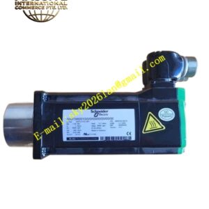
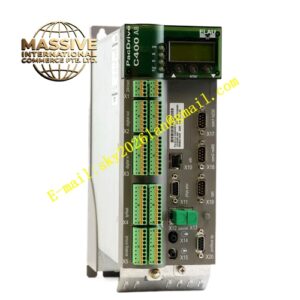
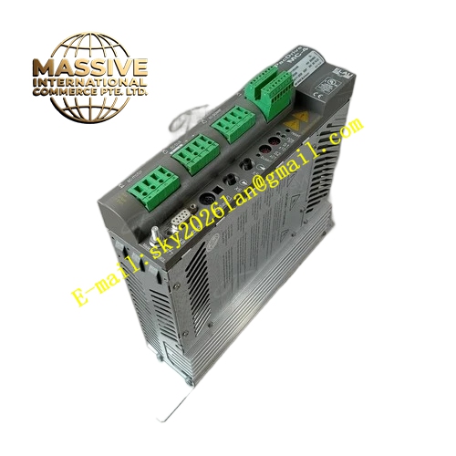
ELAU MC‑4‑11‑03‑400
Technical Specifications Main Circuit Power Supply: 3AC 380‑480V, 50‑60Hz Control Power Supply: DC24V, 1.0A operating current Continuous Output Current: 3A Peak Overload Current: 7.5A for 1‑second duration Output Frequency Range: 0‑600Hz Communication Interfaces: SERCOS fiber‑optic interface, Ethernet service port, multi‑channel digital I/O terminal block Cooling Method: Natural convection cooling Protection Class: IP20 Operating Ambient Temperature: 0℃ to +55℃ Mounting Style: DIN‑rail cabinet mounting
Functional Features Supports position‑control, speed‑control and torque‑control operating modes. Automatic motor‑parameter identification reads electronic nameplate data stored inside ELAU servo motors upon power‑up. SERCOS fiber‑optic communication realizes high‑noise‑immunity microsecond‑level multi‑axis synchronization. Built‑in comprehensive fault‑detection system monitors over‑current, over‑voltage, under‑voltage, over‑temperature and encoder‑signal‑failure conditions. Integrated brake chopper circuit supports connection of external braking resistor to consume regenerative energy. Hardware STO Safe Torque‑Off safety function is integrated. LED status indicators directly display power‑supply status, bus‑link status, operating state and fault‑code information. EPAS‑4 software completes parameter configuration and firmware upgrade operations.
Application Scenarios Medium‑power positioning axes of packaging machinery; printing auxiliary‑drive shafts; multi‑axis‑synchronized automated production lines with medium dynamic requirements.
Performance Parameters Steady‑state speed‑control accuracy reaches ±0.01 %. Short‑term overload capability achieves 250 % of rated continuous output current. Fault‑event logs are stored within non‑volatile on‑board memory. SERCOS communication supports minimum 250‑microsecond real‑time cycle. Regenerative energy generated during motor deceleration dissipates through matched external braking resistor.
Material Composition Aluminum‑alloy die‑cast housing, FR‑4 multilayer printed‑circuit boards, IGBT power‑inverter modules, fiber‑optic transceiver components, metal screw‑lock terminal blocks, SMD LED status‑indicator elements.
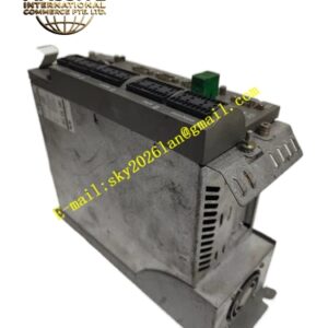
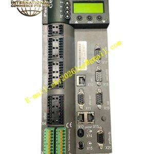
Structural Characteristics Compact vertical DIN‑rail housing. Upper‑housing section holds three‑phase main‑power terminals and motor‑power output connectors. Middle section accommodates SERCOS fiber‑optic sockets and Ethernet service port. Lower‑housing area arranges digital‑input‑output terminals and LED status‑indicator array. Heat dissipation relies on natural convection via housing ventilation slots. Complete part number MC‑4‑11‑03‑400 is printed on metal identification nameplate.
Working Principle Three‑phase AC input power passes through internal rectifier circuit to generate DC bus voltage. IGBT power‑inverter modules convert DC‑bus voltage into adjustable three‑phase AC output to drive connected servo motor. Motion‑setpoint commands are transmitted over SERCOS fiber‑optic bus from upper‑level motion controller. Encoder‑feedback signals return from servo motor to drive for three‑loop closed‑loop calculation. When motor deceleration produces regenerative energy, internal brake chopper switches energy to external braking resistor. Hardware‑monitoring circuits continuously sample voltage, current and temperature values, cut off power output and output fault signals immediately upon detection of abnormal operating conditions.
Installation Requirements Mount unit on standard DIN‑rail inside properly grounded industrial control cabinet. Reserve sufficient surrounding clearance for natural‑convection heat dissipation. Use shielded cables for motor‑power circuit and encoder‑feedback circuit. Separate high‑voltage‑power wiring from low‑voltage‑signal wiring. Observe minimum‑bending‑radius specifications for SERCOS fiber‑optic cables. Select external braking‑resistor resistance and power rating according to actual‑load deceleration‑energy calculation. Ensure reliable protective‑earth connection for drive housing.
Usage Notes Never plug or unplug power terminals and fiber‑optic connectors under powered‑operating condition. Verify firmware‑version compatibility between servo drive and upper‑level PacDrive motion controller before commissioning. Do not block housing ventilation slots. Wear anti‑static wrist straps for maintenance operations targeting internal circuit assemblies. Avoid operating‑environment exposure to conductive dust, heavy oil mist and corrosive industrial vapors.