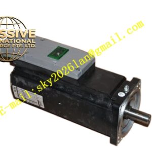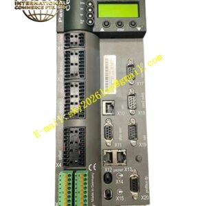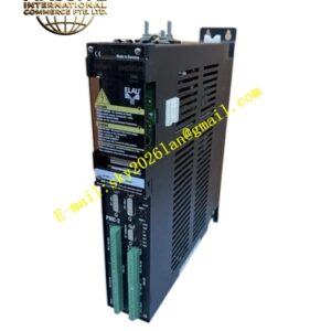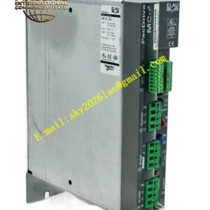
Description
ELAU PMC‑2‑11‑08‑000‑00‑03‑11‑00‑0K
Technical Specifications CPU Processing Core: Real‑time motion‑optimized processor Maximum Controlled Axis Count: 8 axes via SERCOS bus On‑board Digital Inputs: 11 points On‑board Digital Outputs: 8 points Communication Interfaces: SERCOS fiber‑optic interface, Ethernet service port, serial RS232 interface Program Memory: 16MB Data Memory: 8MB Power Supply: DC24V, 1.2A rated consumption Protection Class: IP20 Operating Ambient Temperature: 0℃ to +55℃ Mounting Method: DIN‑rail cabinet installation
Functional Features Combines sequential logic control and hard‑real‑time motion control within single hardware unit. Supports electronic cam profiling, electronic gear synchronization, flying‑shear, mark registration and multi‑axis interpolation functions. SERCOS fiber‑optic bus achieves microsecond‑level synchronization across all controlled axes. Complete IEC‑61131‑3 programming support for multiple programming languages. Non‑volatile memory retains application program and recipe data after power loss. Built‑in system diagnostic functions record controller status, bus errors and axis fault history. Ethernet interface enables program download, online debugging and status monitoring. Supports hot‑swap replacement within compatible PacDrive system architectures.
Application Scenarios Multi‑axis packaging machines; film converting and slitting lines; printing register control systems; automated filling and capping equipment.
Performance Parameters Real‑time motion task cycle reaches 250 microseconds. Inter‑axis synchronization deviation stays below ±1 microsecond. Non‑volatile storage holds up to 1000 historical fault records. Program execution maintains stable timing under full 8‑axis loading condition.
Material Composition Aluminum alloy shielded housing, FR‑4 high‑speed multilayer circuit boards, industrial grade processor chip, fiber‑optic transceivers, non‑volatile flash memory chips, screw‑lock terminal connectors, status LED array.
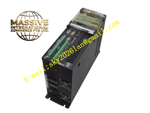
Structural Characteristics Standard DIN‑rail compatible housing with layered internal layout. Front panel exposes status LED indicators, Ethernet service port and RS232 serial connector. Upper edge contains SERCOS fiber‑optic connection ports. Lower section provides pluggable terminal blocks for digital input‑output signals and DC24V power input. Metal nameplate prints complete part number PMC‑2‑11‑08‑000‑00‑03‑11‑00‑0K.
Working Principle User application program stored in flash memory runs on the real‑time processor. Logic tasks handle digital input‑output signal processing and machine sequential workflow. Motion tasks compute position setpoints for each servo axis, then transmit setpoint data to connected MC‑4 servo drives over SERCOS fiber‑optic bus. Feedback status information returns from servo drives back to the controller. On‑board diagnostic modules continuously monitor bus communication quality, I/O signal status and internal hardware health. All critical parameter settings and application programs are saved to non‑volatile flash memory to survive power‑off events.
Installation Requirements Install on standard DIN‑rail inside grounded control cabinet. Leave adequate surrounding clearance for convective cooling. Route fiber‑optic SERCOS cables strictly respecting minimum bending radius specifications. Separate signal cables from high‑power motor cables. Connect DC24V control power supply with correct polarity. Complete reliable protective earth connection for controller housing.
Usage Notes Do not insert or remove fiber‑optic cables while system remains powered. Back‑up application program before performing hardware replacement or firmware update. Operate within defined ambient temperature range. Wear anti‑static wrist straps during maintenance operations. Avoid exposure to conductive dust, oil mist and corrosive gas.