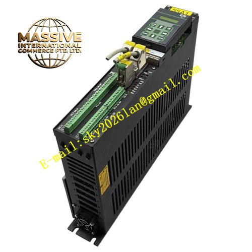
Description
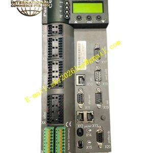
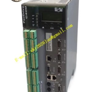
ELAU PMC‑2‑11‑000‑01‑00‑00‑00‑00
Technical Specifications: Three‑phase main supply 400‑480 V AC, rated continuous output current 4 A RMS, peak output current 8 A RMS, control auxiliary power 24 V DC, integrated analog input module 01 option, digital input‑output channels, resolver and Sin‑Cos encoder feedback signal reception, protection class IP20, vertical cabinet‑rail mounting, position‑controller sampling cycle 0.33 ms, operating ambient temperature 0 °C‑45 °C, total unit weight 5.2 kg.
Functional Features: Integrated power driver and positioning motion controller in single hardware unit, supports standalone operation without upper‑level host controller. Executes positioning, electronic gear synchronization and electronic cam curve motion tasks. Accepts resolver and Sin‑Cos motor feedback signals. Equipped with analog input interface for analog motion command. Built‑in rich digital I/O terminals for machine interlock and logic signal processing. Adopts ECL‑3 multitasking motion programming language. Supports memory module for parameter backup and quick device replacement without PC tool. Multiple PMC‑2 units allow DC‑bus parallel connection for power sharing. Comprehensive internal fault diagnosis function facilitates on‑site troubleshooting.
Application Scenarios: Standalone positioning automation stations, packaging machinery single‑axis motion control, printing press auxiliary axis drives, textile machinery synchronized motion axes, special‑purpose machine tool positioning systems.
Performance Parameters: Position‑loop sampling time 0.33 ms, conforms to CE industrial safety certification, supports parameter upload and download via programming tool software.
Material Composition: Cold‑rolled steel sheet metal outer housing, large‑volume aluminum alloy internal heat sink, high‑power IGBT power modules, multi‑layer digital‑analog mixed‑signal printed circuit board, reinforced plastic terminal block components.
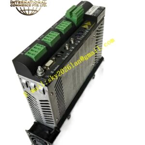
Structural Features: Standard vertical cabinet DIN‑rail mounting form. Main power terminals, signal terminals and option‑module connectors arrange on front‑side area. Internal large‑area aluminum heat sink undertakes power‑circuit heat dissipation. LED indicator lamps on front panel reflect power status and fault alarm information. External memory‑module socket locates at front face for parameter storage.
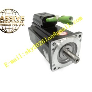
Working Principle: Unit receives motion instructions from internal program, analog input signal or digital I/O trigger. Internal multi‑processor hardware completes position‑loop, speed‑loop and current‑loop real‑time calculation. IGBT power conversion circuit outputs three‑phase sinusoidal current to connected SB‑series servo motor. Motor position‑velocity feedback signal returns to controller to close motion control loop. Built‑in logic processing executes equipment interlock and fault‑response actions simultaneously.
Installation Requirements: Install whole unit within IP54‑rated industrial control cabinet. Mount vertically on standard DIN mounting rail. Maintain sufficient upper‑lower ventilation clearance for heat‑sink heat dissipation. Separate high‑power main‑circuit wiring and low‑voltage signal wiring routing. Complete reliable protective‑earth connection for controller housing. Follow official terminal pin definition strictly when performing power, motor and feedback‑signal wiring.
Usage Notes: Cabinet internal ambient humidity must stay within 5‑85 % non‑condensing range. Do not operate hardware outside rated voltage and rated‑current specification boundaries. Match feedback‑type parameter setting with actual motor feedback hardware. Backup complete parameters into memory‑module before equipment commissioning. Cut off main power supply completely before carrying out wiring modification work.