Description
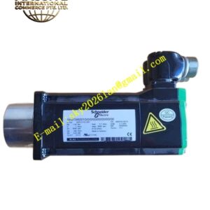
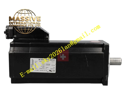
ELAU SM‑100‑50‑030‑P0‑45‑M1‑B1
Technical Specifications: Rated power 1.4 kW, rated speed 5000 rpm, maximum speed 5500 rpm, continuous stall torque 2.6 Nm, peak torque 10 Nm, rotor inertia 2.28 kg·cm², insulation class F, IP65 protection rating, 100 mm B5 mounting flange, 19 mm flat‑key shaft, resolver M1 feedback, power connector P0, built‑in holding brake B1, natural cooling, weight 7.6 kg, ambient operating temperature 0 °C‑40 °C.
Functional Features: Spring‑type holding brake secures shaft static position when power fails. Resolver feedback offers strong immunity against electromagnetic disturbance. Low‑inertia rotor enables rapid speed variation. Internal PTC element executes winding over‑temperature protection. High‑voltage‑winding design reduces working current. Compatible with ELAU PacDrive controller series.
Application Scenarios: Vertical motion axes of packaging lines, automated handling gantries, robotic auxiliary axes, printing press moving units, material lifting mechanisms.
Performance Parameters: Brake static holding torque 8 Nm, brake coil voltage 24 V DC, CE and UL certification, three‑phase 400 V AC supply.
Material Composition: Die‑cast aluminum housing, silicon‑steel‑sheet stator core, rare‑earth permanent‑magnet rotor, copper winding wires, alloy steel output shaft, high‑friction composite brake disc, reinforced plastic connector components.
Structural Features: B5 front‑flange installation structure, separated power and resolver connectors at upper housing, brake module arranged at motor rear end, shaft‑side IP65 sealing assembly, built‑in winding temperature‑sensing device.
Working Principle: Servo drive supplies three‑phase sinusoidal current to stator windings to produce rotating magnetic field which drives permanent‑magnet rotor output torque. Resolver converts rotor mechanical angle into analog signal transmitted to drive for closed‑loop speed‑position regulation. Holding brake locks rotor by spring pressure without 24 V excitation and releases when energized.
Installation Requirements: Fasten motor flange to rigid vibration‑damped mounting base. Keep coupling concentricity deviation under 0.05 mm. Route power cable and feedback cable in different cable ducts. Provide reliable protective earth connection. Leave sufficient surrounding space for heat dissipation. Wire brake power circuit strictly per pin‑out specification.
Usage Notes: Holding brake shall only undertake static‑holding task instead of dynamic stopping. Set drive feedback parameter to resolver mode. Avoid condensation and corrosive‑gas environment. Prohibit hammer striking output shaft during assembly.