Description
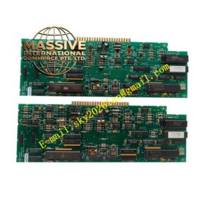
FAS FAS-113AD
Technical Specifications
- Product Type: Analog input module
- Input Signal: 4-20mA analog current signal
- AD Resolution: 12 bit
- Number of Channels: Multi-channel analog input
- Power Supply: 24 VDC
- Diagnostic Function: Wire break and short circuit detection
- Protection Rating: IP20
- Operating Temperature: 0 °C to +60 °C
- Mounting Method: DIN rail rack mounting
Functional Features
- Multiple analog input channels collect 4-20mA signals from field transmitters.
- High precision analog to digital conversion delivers accurate measurement data.
- Continuous loop diagnosis detects wire break and short circuit on field sensor loop.
- Galvanic isolation between field circuit and internal control bus reduces noise interference.
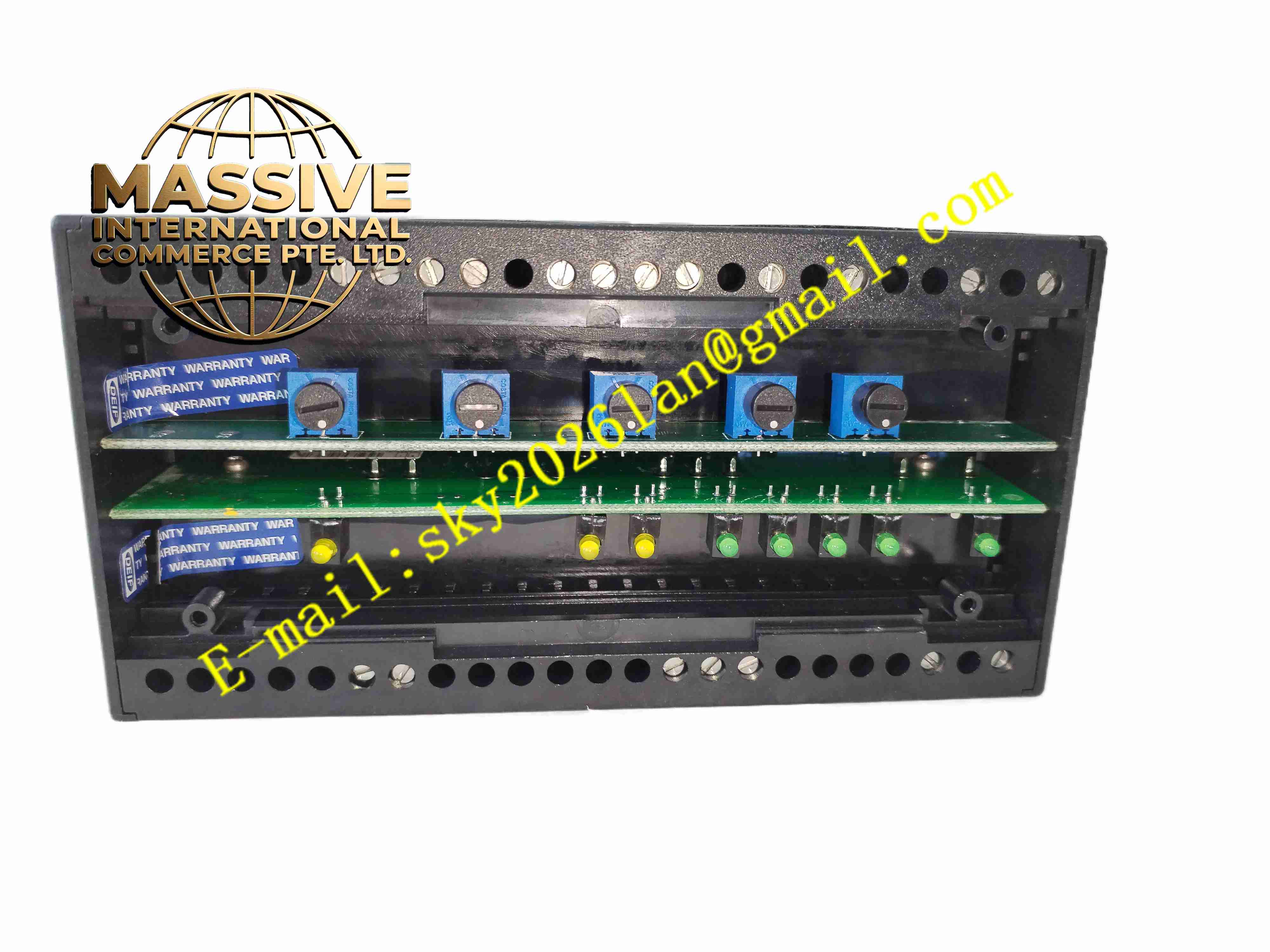
- LED indicators display module power, running status and channel fault.
- Overvoltage and overcurrent protection protects internal circuit from field surge.
- Digital measurement data is transmitted to controller via internal bus.
- Fault signal uploads to controller for alarm and event recording.
- Supports channel range configuration for different transmitter types.
- Compact modular design saves cabinet installation space.
Application Scenarios
- Factory process monitoring system analog signal collection
- Water treatment plant pressure and flow transmitter signal acquisition
- Building automation environment parameter monitoring
- Food and beverage production process measurement
- General industrial automation analog data acquisition
Material Composition
- Housing: Flame-retardant polycarbonate plastic casing
- Main PCB: FR4 printed circuit board
- Conversion chips: 12-bit analog-to-digital converter ICs
- Isolation components: Optocoupler isolation chips
- Terminal block: Copper alloy spring cage wiring terminals
- Backplane connector: Gold-plated copper contact pins
Structural Characteristics
- Vertical modular DIN rail mounting structure.
- Front panel with LED indicators for module and channel status.
- Lower terminal block for field transmitter wiring.
- Rear edge connector connects to rack backplane bus.
- Internal isolation barrier separates field circuit and control logic circuit.
Working Principle 4-20mA current signals from field transmitters enter module input channels. The module samples analog signal and converts analog value to digital data by ADC chip. Diagnostic circuit monitors loop current continuously to detect wiring fault. Valid digital measurement data is sent to controller via backplane bus. Fault information is reported to controller immediately once wiring fault is detected.
Installation Requirements
- Mount module on standard DIN rail inside control cabinet.
- Use shielded twisted pair cable for field transmitter wiring.
- Separate analog signal cables from high power cables.
- Complete protective earth connection for cabinet.
- Verify wiring polarity of each transmitter loop.
- Perform channel test after wiring completion.
- Check backplane connector contact before power on.
Usage Notes
- Do not hot plug module when rack power remains active.
- Do not apply overvoltage to input terminals.
- Keep cabinet dry and free of conductive dust.
- Disconnect field wiring before insulation resistance test.
- Use anti-static protection when handling spare module.
- Replace module immediately when permanent hardware fault occurs.