Description
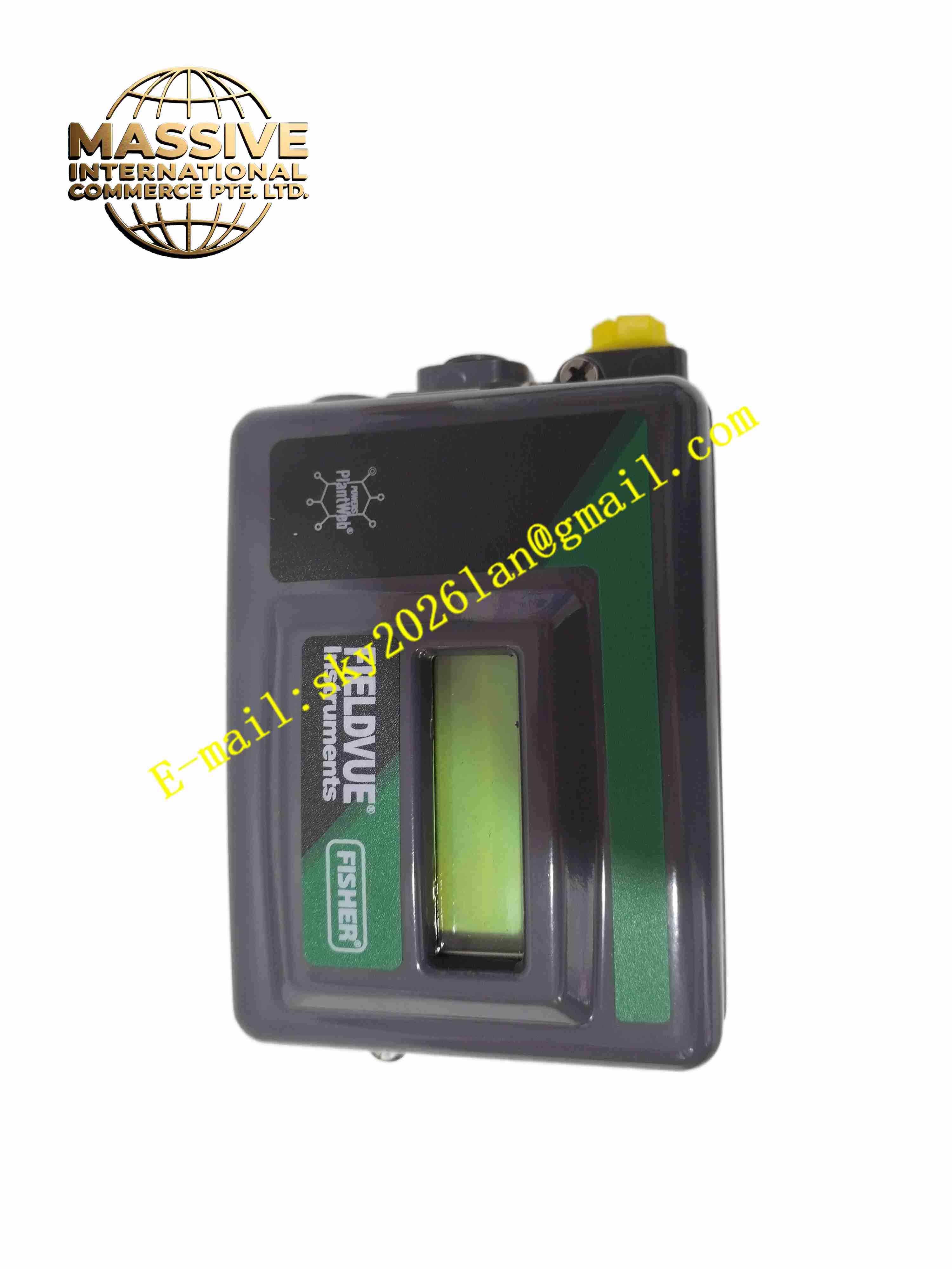
Fisher DVC2000
Technical Specifications
- Product Type: Digital electro-pneumatic valve controller
- Input Signal: 4-20 mA analog current signal
- Supply Air Pressure: 1.4 bar to 10 bar
- Output Type: Pneumatic pressure output to valve actuator
- Position Feedback: Integrated valve stem position sensor
- Communication: HART protocol
- Protection Class: IP66, NEMA 4X
- Operating Temperature: -40 °C to +85 °C
- Certifications: CE, ATEX, IECEx, SIL capable
- Mounting: Direct mount on valve actuator
Functional Features
- High precision valve stem position closed-loop control, reduces positioning error.
- HART digital communication supports remote parameter configuration and diagnostic reading.
- Built-in valve diagnostic function to detect packing friction, actuator leakage and valve sticking.
- Automatic calibration function simplifies on-site commissioning without manual adjustment.
- Fast response to control signal changes for stable process regulation.
- Anti-vibration mechanical structure adapts to plant pipeline vibration environment.
- Over-range protection prevents actuator damage caused by abnormal air pressure.
- Local LCD display shows valve position, signal value and fault status.
- Compatible with single acting and double acting pneumatic actuators.
- Supports partial stroke test for safety valve periodic inspection.
Application Scenarios
- Chemical plant flow, pressure and temperature regulating valves
- Refinery process control loops
- Power plant steam and water control valves
- Oil and gas pipeline regulating valves
- Pharmaceutical and food processing sanitary control valves
Material Composition
- Main housing: Die-cast aluminum alloy with corrosion resistant coating
- Internal pneumatic components: Stainless steel and brass pneumatic valves
- Position sensor: Non-contact magnetic position transducer
- LCD window: Transparent impact-resistant polycarbonate
- Sealing parts: Nitrile or fluorocarbon elastomer gaskets
- Air port fittings: Nickel plated brass
Structural Characteristics
- Compact cast aluminum housing, direct mounting bracket matches standard valve actuators.
- Side air supply port, pneumatic output ports connected to actuator air chambers.
- Front panel with LCD display and local operation push buttons.
- Internal layout separates electronic circuit chamber and pneumatic air circuit chamber.
- Non-contact magnetic position sensor linked to valve stem feedback arm.
- All housing sealing gaskets achieve IP66 dust and water splash protection.
Working Principle 4-20mA setpoint signal is sent to the DVC2000 electronic circuit. The controller compares the setpoint value with actual valve stem position feedback signal. The internal I/P converter converts electrical control signal into pneumatic pressure. The pneumatic amplifier boosts air pressure to drive the valve actuator and adjust valve stem position. The magnetic position sensor continuously feeds back real stem position to form closed loop control. HART communication superimposes digital data on 4-20mA loop for remote configuration and diagnostics.
Installation Requirements
- Mount directly on the top yoke of pneumatic valve actuator.
- Use clean, dry, oil-free instrument air as supply medium.
- Install air filter regulator before the controller to stabilize supply air pressure.
- Route 4-20mA HART signal cable as shielded twisted pair, single end grounding.
- Complete mechanical linkage adjustment between feedback arm and valve stem.
- Perform automatic valve calibration after mechanical installation.
- Keep instrument air pipeline free of moisture and particulate contaminants.
Usage Notes
- Do not use contaminated instrument air containing oil or liquid water.
- Protect the housing from direct strong impact and heavy mechanical load.
- Regularly drain moisture from instrument air filter regulator.
- HART handheld communicator is required for remote parameter modification.
- Perform partial stroke test periodically for safety related valves.
- When disassembling, cut off instrument air supply first.
- Check feedback linkage tightness after valve maintenance.