Description
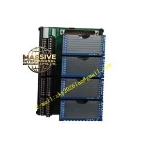
Foxboro DNBTP0971WV
Technical Specifications
- Product Type: Field Terminal Assembly / Wiring Base.
- Module Capacity: Designed to accommodate a specific number of FBM modules (e.g., a row of 8 or 16).
- Bus Connection: Integrates the 2 Mbps redundant module fieldbus connections.
Functional Features
- Integrated Wiring: Combines field termination and backplane bus routing into a single assembly, reducing wiring complexity.
- Module Support: Provides a secure mechanical mounting point and electrical connection for FBM modules.
- Cable Management: Includes provisions for organizing and securing field cables and bus cables.
- Grounding: Provides a common grounding point for the FBM row, ensuring signal integrity.
Application Scenarios
Used in control cabinets to organize and terminate I/O wiring for a complete control loop or a section of a process, streamlining panel layout and maintenance.
Performance Parameters
- Bus Integrity: Maintains the electrical characteristics of the 2 Mbps fieldbus over the length of the baseplate.
- Current Carrying Capacity: Sufficient to handle the aggregate current of all mounted FBM modules and field devices.
Material Composition
Constructed from a rigid, flame-retardant composite material. Internal bus bars are made of high-conductivity copper to minimize voltage drop and signal loss.
Structural Characteristics
A long, rectangular baseplate with a series of evenly spaced connectors for FBM modules. Features terminal blocks on the front or top for field wiring and bus connectors on the ends for daisy-chaining to adjacent baseplates.
Working Principle
The DNBTP0971WV routes field signals from its terminals to the corresponding pins on the FBM connectors. Simultaneously, its internal copper bus bars connect the fieldbus pins of each FBM slot, creating the redundant communication highway that links all modules in the row to the controller.
Installation Requirements
Must be securely mounted to the backpanel of the control cabinet. Fieldbus cables must be connected to the end connectors to form a continuous redundant bus. Field wires must be properly dressed and secured.
Usage Precautions
- Ensure the bus termination resistors are correctly installed at the physical ends of the fieldbus.
- Do not exceed the maximum number of modules per baseplate as specified in the system manual.
- Verify continuity of the fieldbus and ground connections before powering up the system.