Description
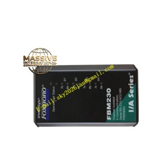
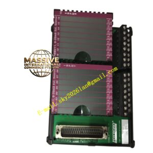
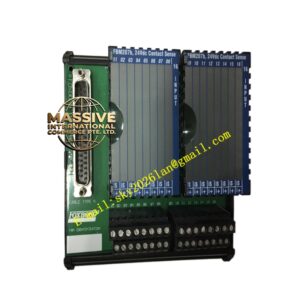
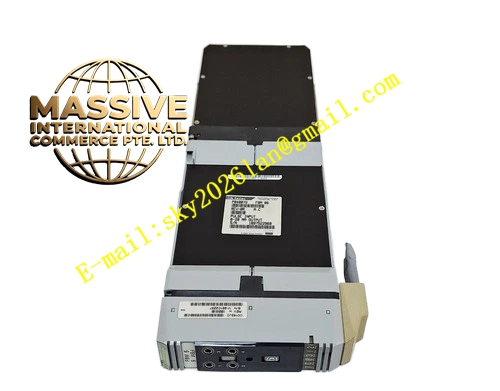
Foxboro FBM06
Technical Specifications
- Product Type: Discrete Input/Output Module.
- Channel Count: Typically 16 or 32 channels per module.
- Voltage Levels: 24VDC, 48VDC, or 120VAC/DC.
- Output Type: Relay or solid-state switching.
Functional Features
- High-Density I/O: Maximizes I/O count per module to save cabinet space.
- Noise Immunity: Built-in filtering prevents false triggering from electrical noise.
- Status Indication: Individual LED per channel for easy field troubleshooting.
- Hot-Swap Capability: Allows for module replacement without shutting down the system.
Application Scenarios
Essential in motor control centers, valve limit switch monitoring, emergency stop circuits, and safety interlock systems across all industrial sectors.
Performance Parameters
- Response Time: Millisecond-level response for fast sequence control.
- Isolation: Group or channel-to-channel isolation to prevent ground loops.
- Reliability: High MTBF for continuous industrial duty.
Material Composition
Opto-isolators for electrical isolation and noise immunity. Rugged terminal blocks or high-density connectors for secure wire retention. Internal PCBs are conformal-coated for environmental protection.
Structural Characteristics
Compact, modular form factor that plugs directly into the I/A Series backplane. Front panel provides clear visual feedback of input/output states and module health.
Working Principle
For inputs, field voltage or contact closure activates an internal opto-isolator, which is then read by the controller. For outputs, the controller’s logic signal activates a relay or solid-state switch to energize or de-energize the connected field load.
Installation Requirements
Install in a designated FBM slot on the backplane. Use appropriate wire gauges for the voltage level. Route wiring away from high-voltage conductors to prevent interference.
Usage Precautions
- Verify voltage polarity for wet contact inputs.
- Check for proper contact rating if switching loads directly.
- Inspect terminals for signs of arcing or overheating during maintenance.