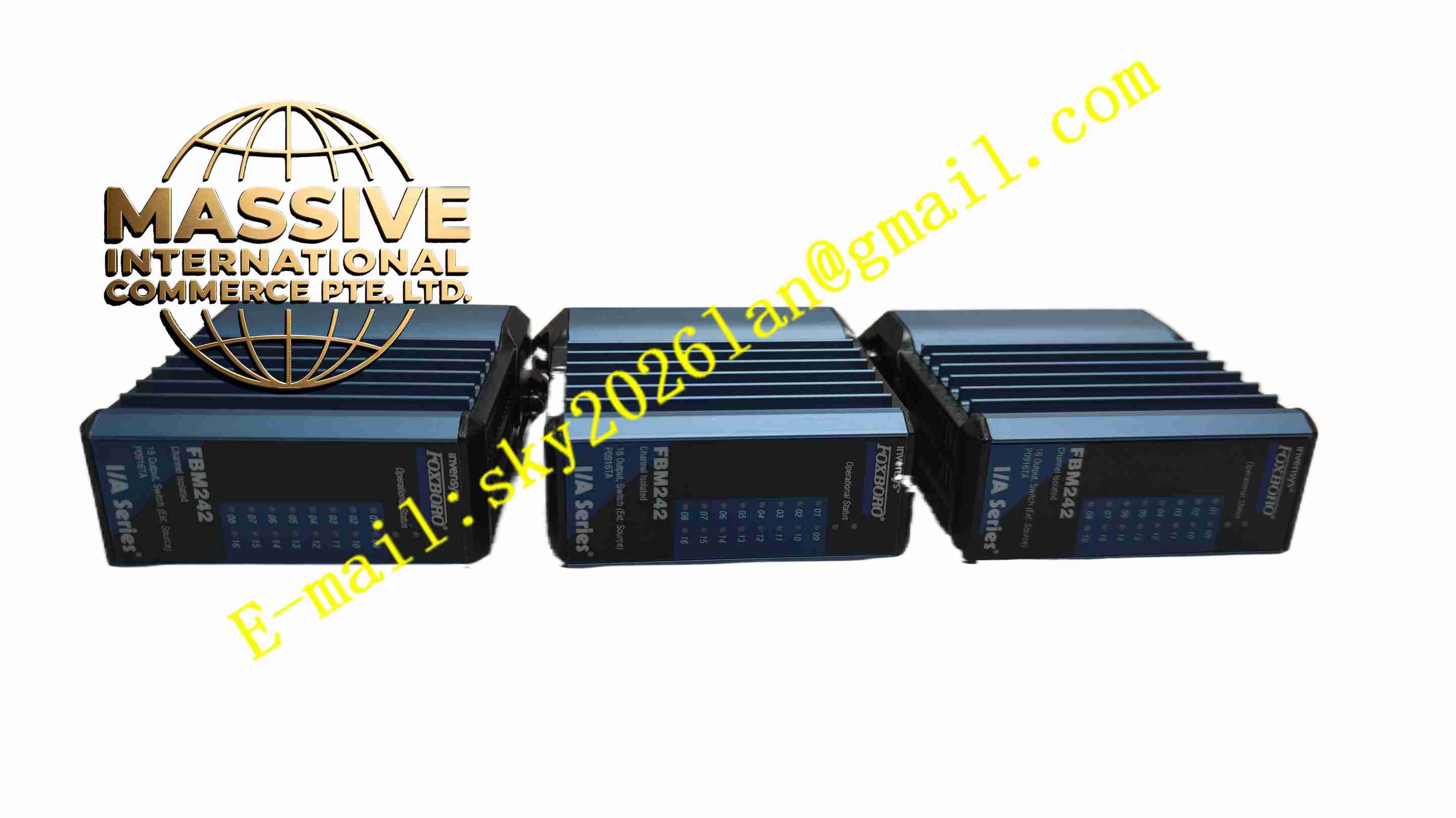
Description
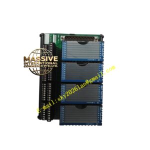
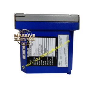
FOXBORO FBM242 RH916TA
Technical Specifications
- Manufacturer: FOXBORO, part of Schneider Electric
- Module Type: FBM242 discrete output module
- Terminal Assembly: RH916TA
- Output Channels: 16 isolated discrete outputs
- Supported Load Voltage: 15 V DC to 60 V DC
- Maximum Load Current: 2.25 A per channel
- On-State Voltage Drop: 0.2 V maximum at 2.25 A
- Off-State Leakage Current: 0.1 mA maximum
- Module Supply Voltage: 24 V DC nominal
- Maximum Power Consumption: 3 W at 24 V DC
- Isolation: Each output channel is electrically isolated from other channels and from ground
- Field Bus Interface: Redundant 2 Mbps module field bus
- Environmental Rating: Designed for G3 harsh industrial environments
- System Integration: Foxboro I/A Series DCS
Functional Features
- Sixteen discrete output channels for field device control.
- Full electrical isolation between channels and ground.
- Supports 15 V DC to 60 V DC discrete loads.
- Per-channel current capability up to 2.25 A.
- Configurable output behavior including continuous and pulsed output modes.
- Fail-safe output configuration options.
- Fault-safe fallback behavior during communication loss or processor fault.
- Input filtering time configuration for associated discrete I/O applications.
- Ladder logic execution support within the FBM application framework.
- Redundant 2 Mbps field bus communication path.
- Continued operation through a single field bus path failure.
- Terminal assembly provides field wiring, current limiting, fusing, and optional relay or solid-state output options.
Application Scenarios
- Emergency shutdown valve control.
- Pump start/stop command output.
- Motor control circuit actuation.
- Solenoid valve switching in process plants.
- Relay drive outputs for interlock systems.
- Alarm horn and beacon control.
- Burner management auxiliary outputs.
- Compressor protection system outputs.
- Utility system on/off control.
- General-purpose discrete actuation in oil and gas, chemical, power, water treatment, and pharmaceutical facilities.
Performance Parameters
- 16 discrete output channels.
- 15 V DC to 60 V DC load voltage range.
- 2.25 A maximum current per channel.
- 0.2 V maximum on-state voltage drop at full load.
- 0.1 mA maximum off-state leakage current.
- 24 V DC module supply.
- 3 W maximum module power consumption.
- Channel-to-channel and channel-to-ground isolation.
- Redundant field bus communication.
- Configurable fail-safe output states.
Material Composition
- Industrial printed circuit board assembly for the FBM242 module.
- Power switching components for discrete output drive.
- Isolation barriers for channel separation.
- Terminal block connectors on the RH916TA assembly.
- Fusing and current limiting components where applicable.
- Metal and engineered plastic housing components.
- Labeling for channel identification and status indication.
Structural Features
- FBM242 module installs into a Foxboro I/A Series field bus module slot.
- RH916TA terminal assembly mounts adjacent to the module for field wiring.
- Screw terminal or plug-in terminal connections for field devices.
- Status indicators for module operation and channel activity.
- Clear channel numbering for wiring identification.
- Modular design supporting replacement without full system shutdown.
- Robust mechanical construction for industrial control cabinets.
Working Principle
The control processor sends discrete output commands over the redundant 2 Mbps field bus to the FBM242 module. The module receives the command, validates it, and energizes the corresponding output channel. Each output acts as an isolated switching device that connects the external load to the field supply voltage. The RH916TA terminal assembly routes the output signal to the field device and provides protection through fusing or current limiting where required. If a field bus path fails, the module continues communication through the remaining active path. If a configured fault condition occurs, the outputs move to a predefined safe state to protect the process.
Installation Requirements
- Install the FBM242 module into a compatible Foxboro I/A Series field bus node.
- Mount the RH916TA terminal assembly according to the system wiring diagram.
- Verify that the field supply voltage matches the load requirements and stays within 15 V DC to 60 V DC.
- Connect field devices to the correct terminal points for each output channel.
- Ensure proper grounding and shielding for control cabinet wiring.
- Configure output behavior, fail-safe states, and filtering parameters in the control system.
- Verify channel isolation and wiring polarity before energizing field loads.
- Perform point-to-point testing after installation.
- Maintain adequate clearance and ventilation inside the control cabinet.
- Use only approved terminal assemblies and spare parts for the family.
Precautions for Use
- Do not exceed 2.25 A per output channel.
- Do not apply AC voltage unless the terminal assembly is specifically configured for relay or AC-rated outputs.
- Verify field supply voltage before connecting loads.
- Use external protection for inductive loads such as solenoid valves and relays.
- Do not bypass fuses or current limiting components in the terminal assembly.
- Confirm fail-safe output settings during system commissioning.
- Avoid wiring field power cables together with sensitive signal cables.
- Replace faulty modules only after confirming system impact and safety requirements.
- Follow Foxboro I/A Series documentation for wiring, configuration, and maintenance.
- Keep environmental conditions within the rated limits for the installed control cabinet.