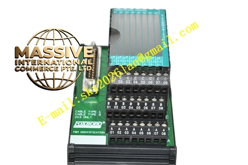
Description
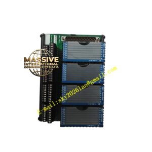
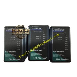
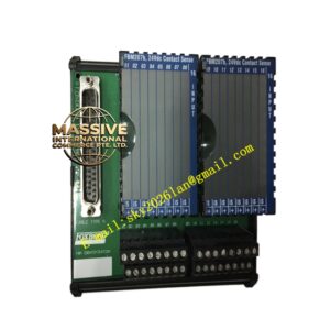
Foxboro FBM246
Technical Specifications
- Module Type: FBM246
- Communication Channels: 8 redundant digital communication channels
- Communication Protocol: Redundant Bidirectional FoxCom
- Module Fieldbus: Redundant 2 Mbps Module Fieldbus
- Redundancy Type: Hardware-level channel and module redundancy
Key Features
- Hardware-Level Redundancy: Eliminates single points of failure by providing redundant communication paths, ensuring seamless failover in case of hardware or communication faults.
- Continuous Smart Device Management: Maintains uninterrupted bidirectional communication for reading multi-variable data, diagnostics, and configuring smart field devices.
- High Reliability: Designed specifically for critical control loops where smart device communication loss is unacceptable.
- Comprehensive Diagnostics: Provides detailed redundancy status and channel-level health monitoring.
Application Scenarios
Essential for safety-critical and high-value process control in refineries, petrochemical plants, and offshore platforms where smart valve positioners and critical transmitters require guaranteed communication availability.
Performance Parameters
- Operating Temperature: 0°C to 60°C
- Storage Temperature: -40°C to 85°C
- Protection Rating: IP20
- Power Supply: 24 VDC redundant backplane supply
Material Composition
Features a robust extruded aluminum enclosure with conformal-coated internal circuitry to withstand high dust, strong electromagnetic interference, and harsh industrial atmospheres.
Structural Characteristics
Standard 200 Series FBM single-width design. Front panel LEDs clearly indicate both communication activity and redundancy status for rapid field diagnostics.
Operating Principle
Operates with continuous cross-monitoring between primary and redundant channels. Upon detecting a fault in the primary path, the system instantly switches to the redundant path without disrupting the control process or smart device communication.
Installation Requirements
Install on a Foxboro 200 Series baseplate. Redundant configuration must be strictly defined in the system software, and redundant field wiring must be properly routed and terminated.
Usage Precautions
Ensure that the redundancy logic is correctly configured in the DCS. Verify that both primary and redundant field connections are secure. Adhere strictly to ESD handling protocols during module replacement.