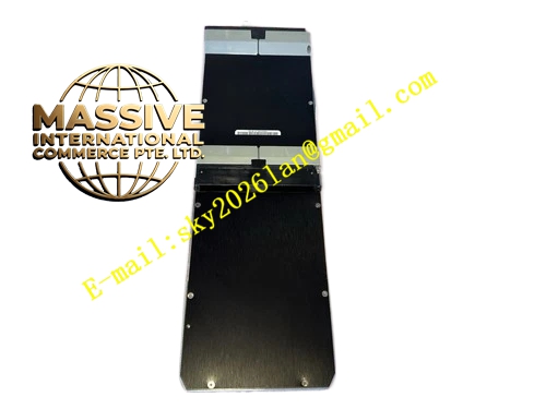
Description
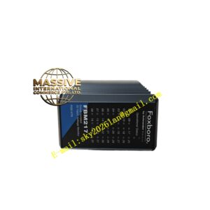
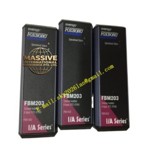
Foxboro FBM25
Technical Specifications
- Module Type: FBM25 Discrete Input
- Channel Configuration: 16 independent discrete input channels
- Signal Compatibility: Dry contacts and 125VDC voltage levels
- Bus Interface: 2 Mbps Redundant HDLC Fieldbus
Functional Features
- High-Density Monitoring: Consolidates 16 discrete signals into a single module, significantly reducing cabinet space and wiring costs.
- Complete Electrical Isolation: Provides high-impedance isolation between channels and the system bus to prevent ground loops and surge damage.
- Real-Time Diagnostics: Continuously monitors channel health, detecting open circuits and short conditions.
- Bit-by-Bit Verification: Ensures absolute data accuracy during bus transmission.
Application Scenarios
Extensively used for monitoring valve limit switches, relay contact statuses, pushbuttons, and safety interlock signals in petrochemical and power generation facilities.
Performance Parameters
- Response Time: Millisecond-level state capture for high-speed sequential control.
- Protection Rating: IP20
- Environmental Tolerance: Certified for G3 harsh environments.
Material Composition
Constructed with industrial-grade flame-retardant housing. Internal circuitry utilizes high-reliability optocoupler isolation, and terminal blocks are made of premium conductive materials for long-term durability.
Structural Characteristics
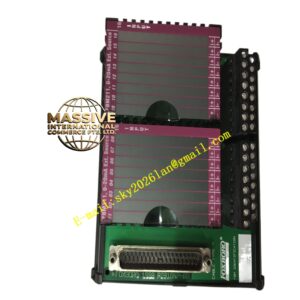
Standard FBM form factor with clear channel labeling and individual LED status indicators on the front panel. Features a precision backplane connector for seamless integration.
Working Principle
External 125VDC or contact closure signals are fed into the module, where they pass through optocoupler isolation circuits. The signals are converted into digital logic levels, packaged, and transmitted over the redundant fieldbus to the controller.
Installation Requirements
Insert into a compatible FBM baseplate. Field wiring must use shielded cables, with the shield grounded at the control cabinet side only to prevent electromagnetic interference.
Precautions for Use
Verify signal types and terminal definitions before wiring. Never apply voltages exceeding the rated 125VDC limit. Always disable the corresponding node in the software before removing the module for replacement.