Description
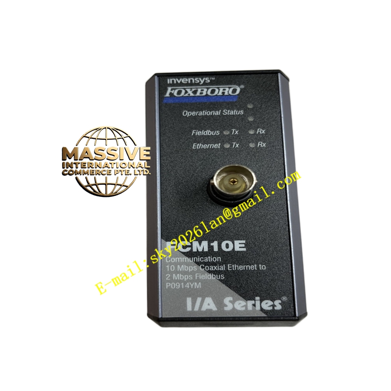
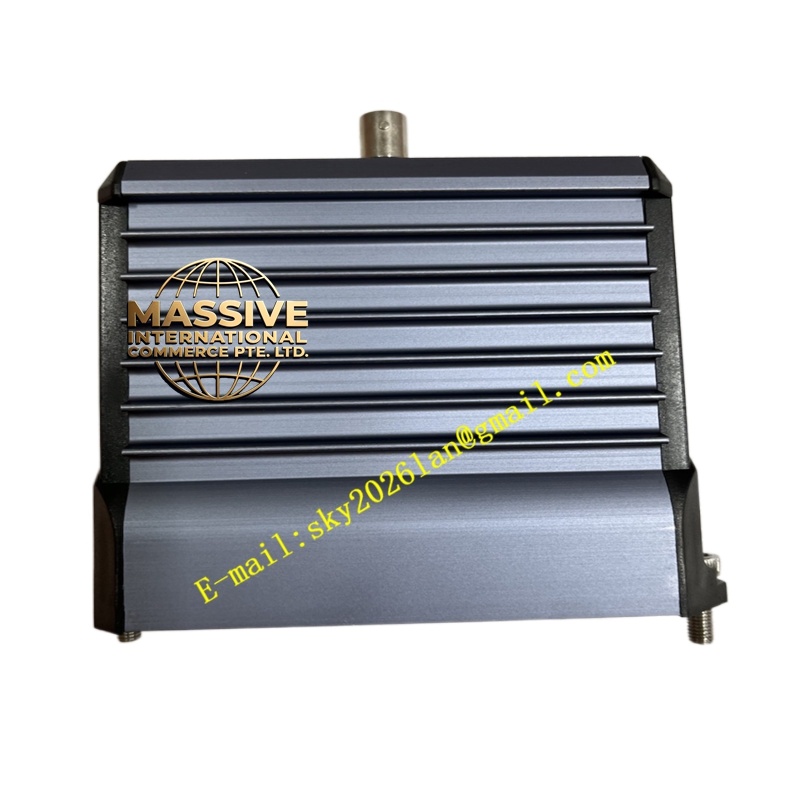
Foxboro FCM10E
Technical Specifications
- Communication Rate: Supports fieldbus transmission rates up to 2 Mbps.
- Node Capacity: Capable of mounting multiple field intelligent devices.
- Isolation Voltage: Features high electrical isolation capabilities to protect communication link safety.
- Operating Temperature: Industrial-grade standard ranging from -40°C to +85°C.
Functional Features
- Bidirectional Communication: Supports two-way data exchange between the master station and field devices.
- HART Pass-Through: Supports transparent transmission of the HART protocol for convenient device diagnostics.
- Fault Isolation: Built-in short-circuit protection and automatic communication fault isolation mechanisms.
- Hot-Swappable: Supports online replacement to minimize system downtime.
Application Scenarios
Ideal for complex industrial environments requiring massive field device integration, such as large-scale oil refineries, natural gas processing plants, and offshore oil platforms for process monitoring and data acquisition.
Performance Parameters
- Communication Latency: Microsecond-level latency ensures real-time performance of control loops.
- Bit Error Rate: Extremely low communication error rate guarantees data transmission integrity.
- Load Capacity: Powerful bus driving capability.
Material Composition
Enclosed in anti-static, anti-aging industrial-grade composite materials. Internal PCBs utilize multi-layer immersion gold plating processes to ensure stable high-frequency signal transmission.
Structural Characteristics
- Compact Form Factor: Saves control cabinet installation space.
- Dedicated Interfaces: Equipped with specialized fieldbus and power interfaces.
- Diagnostic Port: Provides local testing or diagnostic ports for convenient field commissioning.
Working Principle
The FCM10E converts parallel data from the controller into serial bus signals for transmission to field devices via its internal protocol stack. Simultaneously, it parses data returned from field devices and uploads it to the controller, enabling seamless data flow.
Installation Requirements
- Communication cables must use dedicated shielded twisted pairs.
- The shield layer must be properly grounded at a single point on the module side.
- Avoid installing communication modules near frequency converters or high-power motors.
Usage Precautions
- Ensure the bus topology complies with specifications, avoiding excessively long stub lines.
- When expanding the network, confirm that bus termination resistors are configured correctly.
- Regularly monitor communication status indicator lights; investigate any abnormal flashing immediately.