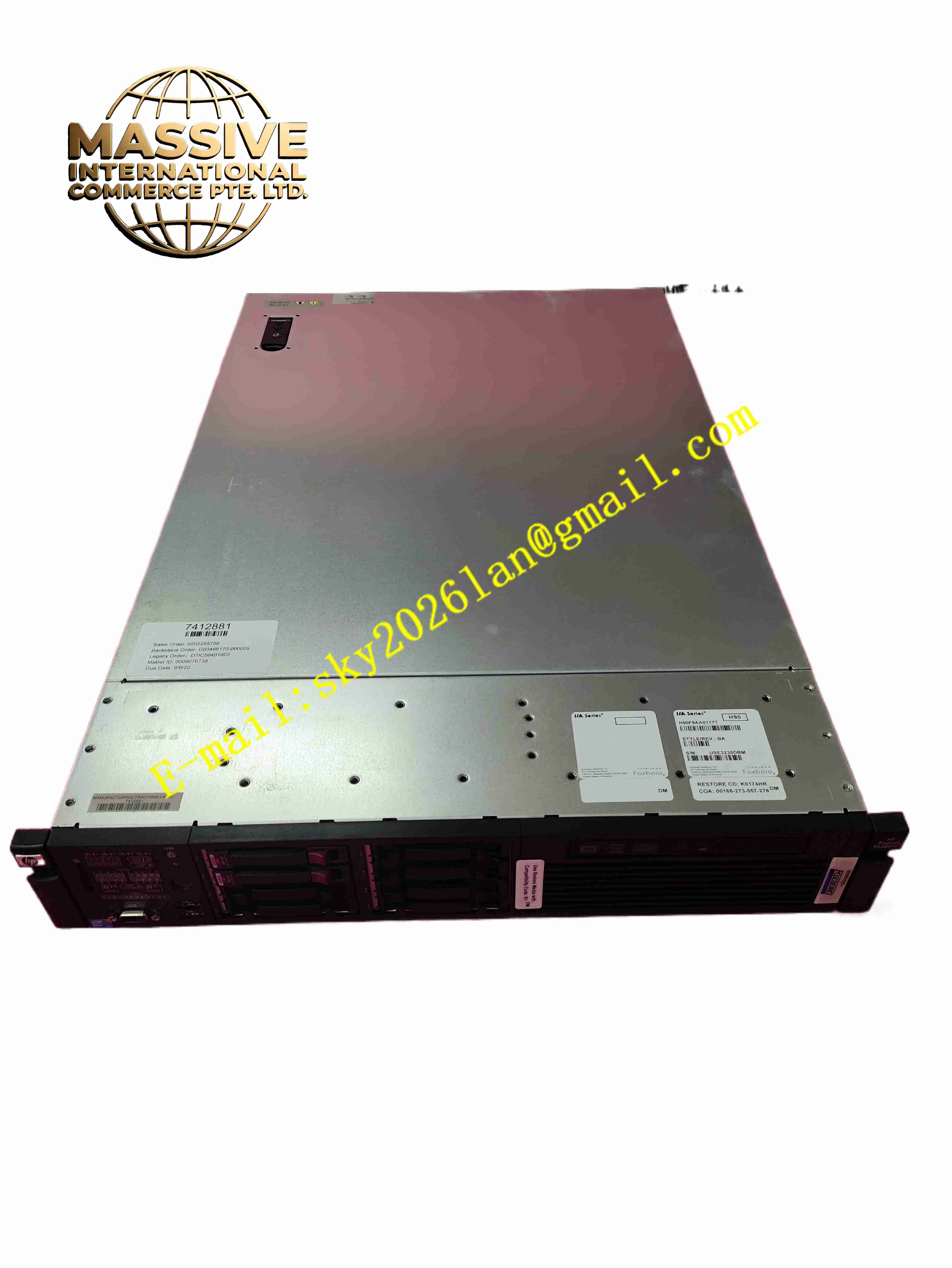
Description
Foxboro H90 H90C9AA0117S
Technical Specifications
- Product Type: Intelligent differential pressure transmitter
- Sensing Technology: Capacitive pressure sensor
- Output Signal: 4-20 mA analog with HART 7 digital communication
- Power Supply: 12 V DC to 42 V DC loop powered
- Reference Accuracy: ±0.075 % of calibrated span
- Turn-down Ratio: Up to 100:1
- Process Wetted Material: 316L stainless steel standard
- Housing Material: Die cast aluminium alloy with epoxy coating
- Protection Rating: IP67, NEMA 4X
- Operating Process Temperature: -40 °C to +120 °C
- Ambient Operating Temperature: -40 °C to +85 °C
- Communication Protocol: HART 7
- Mounting: 2 inch pipe mounting bracket or panel mounting
Functional Features
- High precision capacitive sensor measures differential pressure for liquid level, flow and pressure measurement.
- 4-20 mA loop current output proportional to measured differential pressure.
- HART digital communication supports remote parameter configuration, tag setup and diagnostic reading.
- Wide turn-down ratio allows large adjustment of measurement range without sensor replacement.
- Built-in temperature compensation minimises measurement drift caused by ambient and process temperature variation.
- Sensor fault detection identifies overrange, sensor damage and loop wiring fault.
- Digital damping function stabilises output signal for turbulent or noisy process conditions.
- Non-volatile memory stores calibration data, tag, range and unit setting.
- Overpressure protection withstands high static line pressure without permanent sensor damage.
- Local LCD display shows process variable, percentage span and diagnostic code.
Application Scenarios
- Petrochemical plant orifice plate differential pressure flow measurement
- Tank liquid level measurement using differential pressure
- Power plant boiler drum level and feedwater flow monitoring
- Refinery process pipeline differential pressure monitoring
- Water treatment plant filter differential pressure measurement
Material Composition
- Wetted parts: 316L stainless steel sensor diaphragm and process flanges
- Sensor core: Capacitive ceramic sensing element
- Transmitter housing: Die cast aluminium alloy with epoxy powder coating
- Main PCB: FR4 printed circuit board with conformal coating
- Display window: Polycarbonate transparent window
- Gasket: FKM fluorocarbon elastomer sealing gasket
- Terminal block: Tin-plated copper alloy screw terminals
Structural Characteristics
- Split structure with process flange assembly and electronic housing.
- Rotatable electronic housing allows local display orientation adjustment.
- Dual process pressure ports for high side and low side process connection.
- Internal isolation diaphragm transfers process pressure to capacitive sensing cell.
- Electronics compartment sealed by gasket to achieve IP67 ingress protection.
- Internal circuit layout separates low level sensor signal circuit and HART communication circuit.
Working Principle Process pressure from high side and low side ports acts on isolation diaphragms. Hydraulic fill fluid transmits pressure difference to capacitive sensing cell. Capacitance value changes proportionally to differential pressure. Onboard microcontroller samples capacitance signal, applies temperature compensation and converts value to calibrated differential pressure. The circuit controls 4-20 mA loop current output. HART modem superimposes digital communication signal onto analog current loop for remote configuration and diagnostics. When sensor fault occurs, transmitter outputs specified fault current level.
Installation Requirements
- Mount transmitter on 2 inch pipe bracket or panel according to process piping layout.
- Route impulse tubing to high and low pressure ports, remove air or liquid trap from impulse line.
- Connect 4-20 mA loop power and HART communication wiring to terminal block.
- Torque housing cover screw to specified torque to maintain IP67 sealing integrity.
- Perform zero and span calibration after installation and impulse line purging.
- Verify HART communication connection and local display reading.
- Test output signal across full calibrated measurement range.
Usage Notes
- Do not exceed maximum static pressure and sensor overpressure rating.
- Use compatible gasket material for process fluid and temperature.
- Re-calibrate transmitter after impulse piping maintenance or sensor replacement.
- Keep housing cover closed and gasket intact to prevent moisture ingress.
- Use HART communicator with proper loop resistance for remote configuration.
- Protect transmitter housing from direct heavy mechanical impact.
- Replace transmitter sensing assembly immediately when permanent sensor damage occurs.