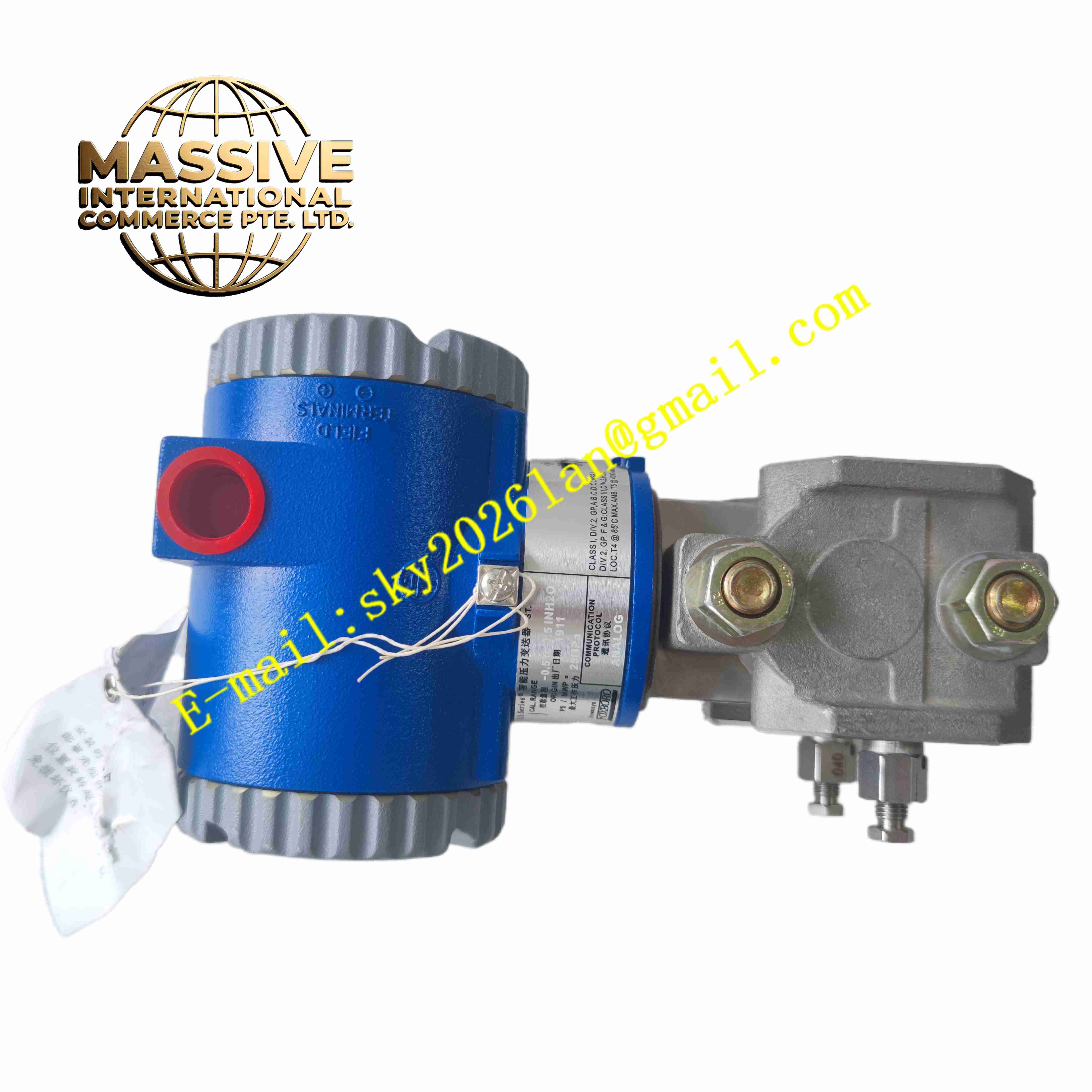
Description
Foxboro IDP10-A22A01F-M1
Technical Specifications
- Product Type: Intelligent 2-wire differential pressure transmitter
- Measurement Accuracy: ±0.05% of reading
- Turndown Ratio: 400:1
- Response Time: 125 ms
- Maximum Static Working Pressure: 3000 psi / 207 bar
- Long Term Drift: ±0.03% of span per year for 10 years
- Output Signal: 4 mA to 20 mA analog with HART digital overlay
- Power Supply: 10.8 V DC to 42 V DC, loop powered
- Ingress Protection: IP67, NEMA 4X
- Operating Temperature: -40 °C to +85 °C
- Communication Protocol: HART, FOUNDATION Fieldbus optional
- Safety Certification: SIL2 TÜV Rheinland certified per IEC 61508
- Mounting Method: Direct mount, low profile or biplanar manifold mounting
- Weight: 3.2 kg
Functional Features
- High precision differential pressure measurement for flow, liquid level and density calculation.
- Two-wire loop powered design reduces field wiring quantity.
- HART digital communication supports remote parameter configuration, diagnostic reading and calibration.
- Wide turndown ratio covers multiple measurement ranges without transmitter replacement.
- Built-in temperature compensation eliminates measurement deviation caused by ambient temperature fluctuation.
- On-board LCD display shows real-time process value, percentage span and fault code.
- Sensor self-diagnosis continuously monitors sensor health and circuit integrity.
- Zero and span calibration can be executed via local push buttons or remote HART master.
- NACE compliant wetted parts resist sulfide stress cracking in sour gas applications.
- IP67 enclosure protects electronics against dust ingress and water splash.
Application Scenarios
- Petrochemical plant orifice plate flow measurement
- Refinery tank differential pressure liquid level monitoring
- Natural gas pipeline pressure difference and flow calculation
- Power plant boiler feed water flow measurement
- Chemical reactor density and liquid level differential pressure monitoring
Material Composition
- Wetted diaphragm: Hastelloy C276
- Process body: 316L stainless steel
- Housing: Low copper aluminium alloy with anti-corrosion coating
- Internal circuit board: FR4 PCB with conformal coating
- Sensor element: Capacitance type differential pressure sensing cell
- Sealing components: Fluorocarbon elastomer gaskets
- Display window: Scratch resistant polycarbonate panel
Structural Characteristics
- Split structure including process sensing body and upper electronic housing.
- Rotatable electronics housing allows local display orientation adjustment.
- Dual isolation diaphragm structure isolates sensing cell from corrosive process medium.
- Internal pressure transmitting oil fills the cavity between diaphragm and sensing cell.
- Local push button interface embedded on the top housing for field operation.
- Threaded process connection for direct mounting to manifold or impulse piping.
Working Principle High pressure and low pressure medium act on two sides of the sensing diaphragm. The diaphragm deflects proportionally to differential pressure. The capacitance sensing cell converts mechanical deflection into capacitance variation. The microprocessor calculates differential pressure value after temperature compensation and linearization. The transmitter outputs 4-20mA current signal proportional to measured differential pressure, and superimposes HART digital signal on the current loop for bi-directional digital communication.
Installation Requirements
- Install the transmitter on solid support bracket or 3-valve / 5-valve manifold.
- Arrange impulse piping with proper slope to eliminate trapped gas or liquid.
- Use shielded twisted pair cable for 4-20mA HART loop wiring.
- Separate instrument signal cable from high voltage power cable.
- Complete protective earth connection for transmitter metal housing.
- Perform zero calibration after piping installation and pressure stabilization.
- Verify HART communication connection with DCS system after wiring completion.
Usage Notes
- Do not apply pressure exceeding maximum static pressure rating to the sensing diaphragm.
- Keep housing cover thread sealed tightly to maintain IP67 protection.
- Disconnect loop power before opening electronics housing cover.
- Use anti-static wristband when handling internal electronic components.
- Avoid sudden pressure shock to the diaphragm during commissioning.
- Inspect impulse piping and gaskets periodically for medium leakage.
- Replace transmitter immediately when permanent sensor drift or circuit failure occurs.