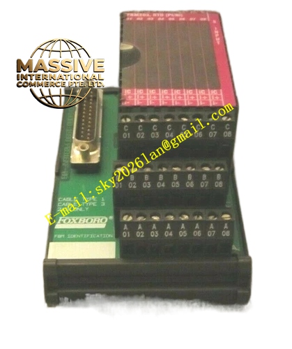
Description
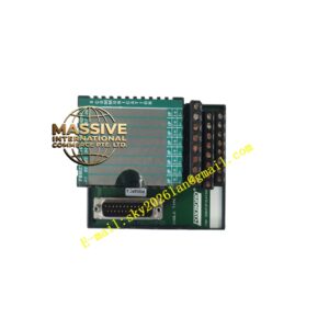
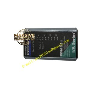
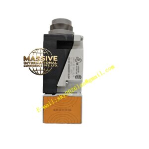
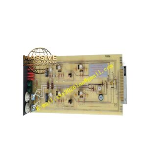
Foxboro P0916AE
Technical Specifications
- Terminal Type: Compression screw terminals.
- Wire Gauge Compatibility: Supports 24 to 14 AWG (0.5 to 2.5 mm²) conductors.
- Operating Temperature Range: -20°C to +60°C.
- Mounting Method: Standard 35 mm DIN-rail or baseplate mount.
- Power Requirements: None (completely passive device).
Functional Features
- Direct FBM Mapping: Terminal arrangement perfectly matches the I/O channel assignment of the installed FBM, significantly simplifying loop checks.
- Tool-Friendly Terminations: Designed for use with standard screwdrivers and tube ferrules for optimal contact.
- Shield and Ground Provisions: Includes dedicated connection points for cable shields to enhance noise immunity in analog applications.
- Serviceable Design: Features clear terminal numbering and ample space for labeling to reduce wiring errors.
Application Scenarios
Widely utilized in Oil & Gas (wellhead I/O marshalling, tank farms), Chemicals & Refining (analog loops for temperature/pressure), Power Generation, and Water/Wastewater treatment facilities where robust field wiring is critical.
Performance Parameters
- Terminal Torque: Typical tightening torque of 0.4 to 0.6 Nm.
- Vibration Resistance: Screw-compression terminations remain tight in high-vibration environments, preventing intermittent faults.
- Signal Compatibility: Supports the I/O type of the installed FBM (analog, discrete, pulse).
Material Composition
Constructed with high-grade, flame-retardant industrial plastics for the insulating base, and premium copper-alloy contacts with corrosion-resistant plating to ensure long-term low contact resistance.
Structural Characteristics
- Compact Form Factor: Lightweight, single-FBM footprint.
- Modular Interface: Seamlessly docks with compatible Foxboro I/A Series FBMs.
- Labeling Area: Integrated clear identification zones for maintenance teams.
Working Principle
As a passive component, the P0916AE relies purely on mechanical compression. When the screw is tightened, it forces the wire (typically with a ferrule) against a metal contact plate, creating a permanent, low-resistance electrical pathway and grounding route without any active signal processing.
Installation Requirements
- Install in a clean, ventilated control cabinet maintaining temperatures within the FBM’s operating range.
- Use end-stops on the DIN rail to prevent lateral movement during maintenance.
- Always use recommended tube ferrules for stranded wires to prevent fraying.
Usage Precautions
- Periodically re-check screw tightness, especially after initial thermal cycling.
- Inspect for corrosion or dust accumulation during routine maintenance.
- Keep at least one spare base per panel section to expedite recovery if a terminal is damaged during field work.