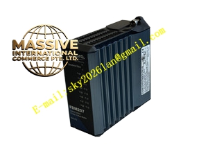
Description
Foxboro PO400ZG
Technical Specifications
- Operating Voltage: 12-24 VDC.
- Input Range: ±10V, ±5V.
- Output Range: 4-20mA.
- Communication Rate: 2 Mbps fieldbus.
- Accuracy: ±0.05%.
Functional Features
- High-Frequency Response: Frequency response up to 100kHz, suitable for rapidly changing process control.
- High Reliability: Designed specifically for harsh industrial environments to ensure long-term stable operation.
- Flexible Configuration: Supports conversion of multiple analog signal inputs and outputs.
Application Scenarios
Applicable in manufacturing, process automation, and various industrial environments requiring high-precision analog monitoring and control.
Performance Parameters
- Data Throughput: Supports high-speed data exchange to meet real-time control demands.
- Signal Isolation: Provides electrical isolation between channels and channel-to-ground.
Material Composition
Constructed from industrial-grade flame-retardant materials and high-reliability electronic components. Circuit boards are treated with conformal coating to resist moisture, dust, and corrosive gases.
Structural Characteristics
- Modular Design: Supports DIN rail or wall-mounted installation.
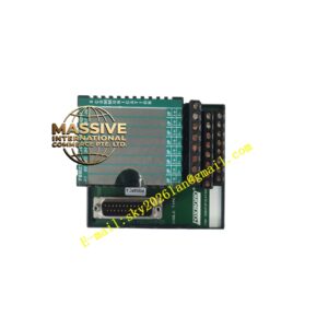
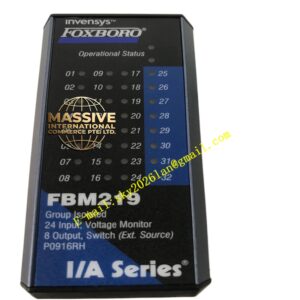
- Status Indicators: Equipped with LEDs on the front panel to intuitively display operating status and communication conditions.
Working Principle
The PO400ZG receives analog signals from field devices, converts them into digital signals, and transmits them to the controller via the node bus. Simultaneously, it receives digital commands from the controller and converts them into 4-20mA analog signals to drive field actuators.
Installation Requirements
- Must be correctly connected to the A/B dual channels of the redundant node bus.
- Analog signal wires must use shielded cables and be routed away from power lines.
- Ensure the module power supply voltage is stable within the 12-24 VDC range.
Usage Precautions
- Strictly prohibited to short-circuit the voltage output terminals.
- Ensure input/output ranges match the actual field devices during configuration.
- Regularly check the module’s communication status and indicator lights.