Description
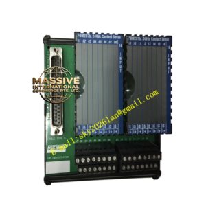
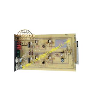
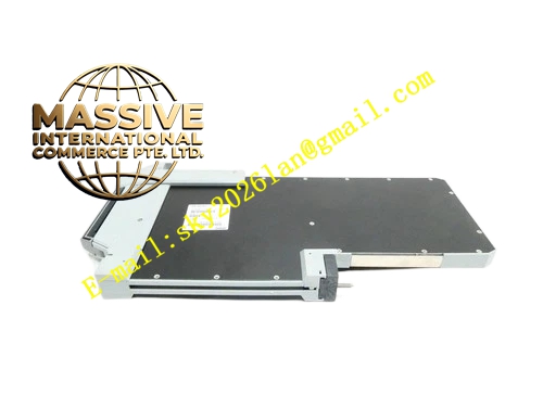
Foxboro SY-0303460E
Technical Specifications
- Product Type: Field Wiring Terminal Block Assembly.
- Channel Capacity: Multi-channel configuration for analog and discrete I/O.
- Voltage Rating: Rated for 300V AC/DC industrial control applications.
- System Compatibility: Direct mating with Foxboro FBM and I/O modules.
Functional Features
- Secure Termination: Provides a gas-tight connection that prevents oxidation and ensures long-term electrical reliability.
- Modular Design: Allows for easy replacement of individual terminal sections without rewiring the entire assembly.
- Integrated Protection: Often includes provisions for fuses, surge suppressors, or isolation barriers.
- Visual Diagnostics: Features color-coded markers and LED test points for rapid field troubleshooting.
Application Scenarios
Essential in any Foxboro I/A Series control cabinet, particularly in outdoor skids, remote I/O stations, and harsh environments where connection integrity is paramount.
Essential in any Foxboro I/A Series control cabinet, particularly in outdoor skids, remote I/O stations, and harsh environments where connection integrity is paramount.
Performance Parameters
- Contact Resistance: Extremely low milliohm-level resistance to prevent signal attenuation.
- Vibration Resistance: Engineered to maintain clamp pressure in high-vibration environments (e.g., near compressors or turbines).
- Insulation Resistance: >100 MΩ at 500VDC to prevent cross-channel interference.
Material Composition
The housing is molded from glass-filled, UL94 V-0 flame-retardant polycarbonate. The current-carrying clamps are made of high-conductivity copper alloy with tin or silver plating to prevent corrosion and ensure low contact resistance.
The housing is molded from glass-filled, UL94 V-0 flame-retardant polycarbonate. The current-carrying clamps are made of high-conductivity copper alloy with tin or silver plating to prevent corrosion and ensure low contact resistance.
Structural Characteristics
A compact, linear arrangement of individual terminal points mounted on a sturdy metal or plastic carrier frame. The front features clearly labeled, recessed screw heads or spring-actuated levers, while the rear provides solderless IDC (Insulation Displacement Connection) or screw terminals for the internal harness.
A compact, linear arrangement of individual terminal points mounted on a sturdy metal or plastic carrier frame. The front features clearly labeled, recessed screw heads or spring-actuated levers, while the rear provides solderless IDC (Insulation Displacement Connection) or screw terminals for the internal harness.
Working Principle
The assembly mechanically clamps the stripped end of a field wire against a conductive metal bar. This creates a permanent, low-resistance electrical path. The modular carrier ensures that each signal is physically and electrically isolated from its neighbors, preventing short circuits and crosstalk.
The assembly mechanically clamps the stripped end of a field wire against a conductive metal bar. This creates a permanent, low-resistance electrical path. The modular carrier ensures that each signal is physically and electrically isolated from its neighbors, preventing short circuits and crosstalk.
Installation Requirements
Mount the assembly securely on a standard DIN rail or backplane panel. Strip the field wire to the exact length specified to ensure the conductor is fully seated under the clamp without exposing bare wire. Use ferrules for stranded wire to prevent fraying.
Mount the assembly securely on a standard DIN rail or backplane panel. Strip the field wire to the exact length specified to ensure the conductor is fully seated under the clamp without exposing bare wire. Use ferrules for stranded wire to prevent fraying.
Usage Precautions
- Do not over-torque terminal screws, as this can strip the threads or damage the wire.
- Periodically inspect terminals for signs of thermal discoloration, which indicates a loose connection.
- Ensure the assembly is properly grounded if it includes a shield termination bar.