Description
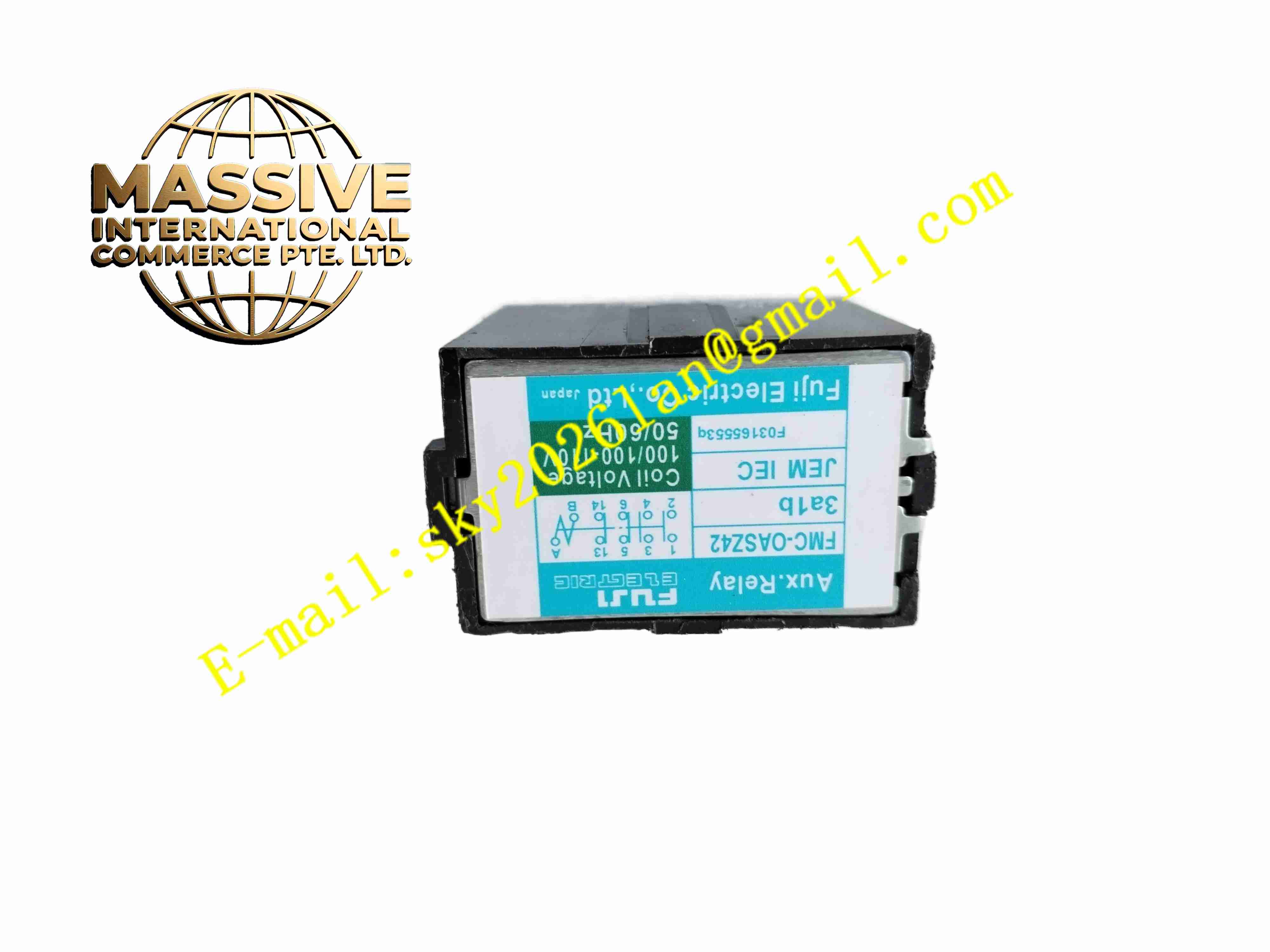
Fuji FMC-OASZ42 3A1B
Technical Specifications:
- Contact Configuration: 3A1B (3 NO, 1 NC)
- Rated Thermal Current: 10 A
- Maximum Rated Voltage: 600 VAC
- Coil Voltage: 100–110 VAC, 50/60 Hz
- Coil Pick-up VA: 9–11 VA
- Coil Holding VA: 2–3 VA
- Contact Closing Time: 10 ms to 20 ms
- Contact Opening Time: 5 ms to 15 ms
- Minimum Switching Current: 3 mA
- Operating Temperature: -20 °C to +60 °C
- Storage Temperature: -40 °C to +85 °C
- Mechanical Life: 10,000,000 operations
- Electrical Life: 1,000,000 operations under rated load
Function Features:
- 4-pole multi-contact design with three normally open and one normally closed contacts
- Silver alloy contact material reduces contact arcing and extends service life
- Fast response speed for high-speed control interlock circuits
- Compact body saves cabinet wiring space
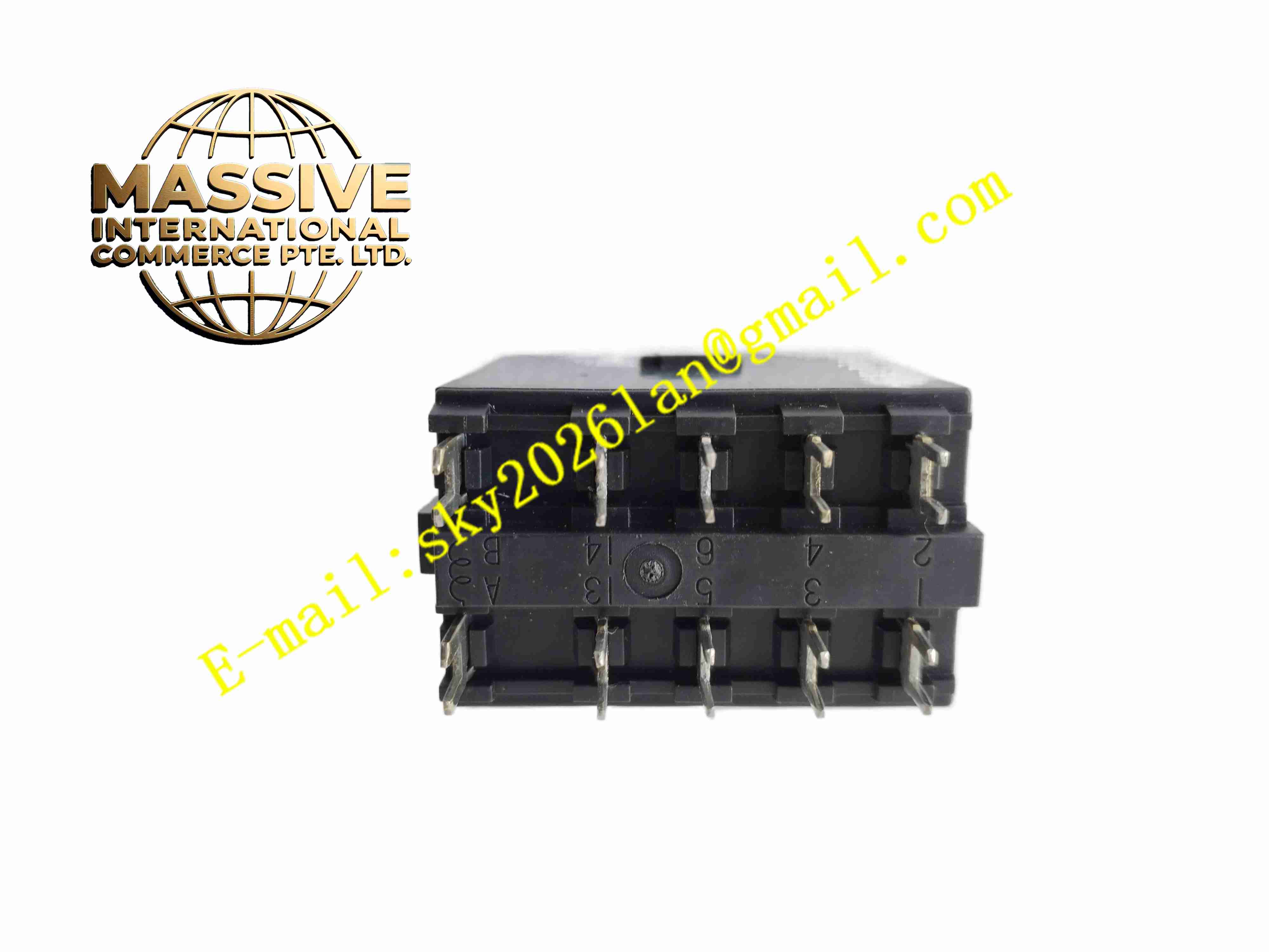
- Clear terminal marking for simple wiring identification
- Coil surge suppression circuit reduces electromagnetic interference
- Compatible with Fuji contactor accessory mounting base
- Stable contact performance under vibration environment
Application Scenarios:
- Motor control cabinet auxiliary signal expansion
- PLC output signal amplification for contactor driving
- Boiler and burner control interlock circuits
- Factory automation control panel logic conversion
- Power distribution protection secondary control circuits
Material Composition:
- Housing: Flame retardant thermoplastic resin enclosure
- Contact Material: Silver alloy contacts
- Coil: Copper enameled wire wound on laminated iron core
- Terminal Blocks: Copper alloy screw terminals with tin plating
- Internal Frame: Reinforced plastic insulation frame
- Spring Components: Stainless steel contact pressure springs
Structural Features:
- Compact rectangular plastic housing for DIN rail mounting
- Screw terminal blocks arranged on the bottom side for field wiring
- Internal moving contact armature driven by electromagnetic coil
- Separated coil chamber and contact chamber to prevent arc interference
- Snap-on DIN rail clip for fast installation and removal
- Top marking area printed with contact configuration and coil rating
Working Principle: When rated voltage applies to the relay coil, electromagnetic force pulls the armature to move. The armature drives contact springs to close the three normally open contacts and open the normally closed contact. When coil power cuts off, the return spring pushes the armature back to original position. All contacts reset to their idle state. The contact switching action transfers control signals to secondary field devices.
Installation Requirements:
- Mount relay on standard 35 mm DIN rail inside control cabinet
- Keep relay upright during installation to maintain contact mechanical performance
- Tighten terminal screws with specified torque to avoid loose connections
- Separate relay coil wiring from high power main circuit cables
- Maintain ventilation space around relay to prevent heat accumulation
- Avoid installation location with heavy mechanical vibration
Usage Notes:
- Verify coil voltage matches control circuit voltage before power application
- Do not exceed rated contact current and voltage limits
- Check contact condition regularly under frequent switching cycles
- Use external surge suppression components for inductive loads
- Disconnect control power before wiring modification
- Keep cabinet clean to prevent dust accumulation on contact surfaces