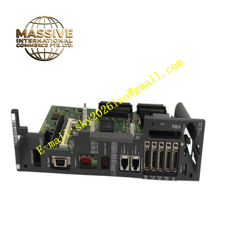
Description
GE A16B-3200-0600
Technical Specifications Dual Ethernet communication ports; onboard CPU and memory chips; robot system firmware storage interface; backplane bus connector for robot rack; multiple peripheral signal connectors; 24V DC logic power supply.
Functional Features Runs robot operating system and user teach programs. Calculates joint trajectory and inverse kinematics for robot arms. Sends motion setpoint commands to servo amplifier units via system bus. Uploads robot status, alarm logs and position data over Ethernet. Receives operation commands and parameter settings from the teach pendant. Performs continuous self-diagnosis of onboard memory and peripheral interfaces.
Application Scenarios Fanuc R-30iA series six-axis industrial robot controllers used for welding, handling, assembly and palletizing.
Performance Parameters High-speed trajectory interpolation calculation; low communication latency with servo drives; stable network data transmission; high diagnostic coverage of onboard hardware faults.
Material Composition PCB substrate is high-reliability FR-4 multilayer board; main processor and memory chips are industrial wide-temperature semiconductors; Ethernet and bus connector contacts are gold-plated; surface components are protected by conformal coating.
Structural Characteristics Rectangular rack plug-in motherboard; front panel with two Ethernet RJ45 ports, USB port and status LEDs; rear gold finger connector connecting with robot controller backplane; on-board memory chips and flash storage modules soldered on PCB.
Working Principle The CPU loads robot system firmware and user programs from onboard flash memory. It reads robot joint feedback data from servo units, computes motion trajectories and outputs real-time motion commands. It exchanges data with the teach pendant and external host through Ethernet and serial peripherals. The onboard diagnostic circuit monitors power supply, memory and communication link integrity.
Installation Requirements Cut off robot controller main power before board replacement. Align gold fingers with the designated slot and insert smoothly. Lock front panel latches to maintain stable contact. Restore robot system software and parameter backup after replacement. Perform robot zero point calibration before resuming production.
Precautions for Use Handle with anti-static wrist strap at all times. Do not touch gold-plated edge connectors. Store robot parameter backup files before removal. Do not hot-swap this main CPU board while the controller is powered.