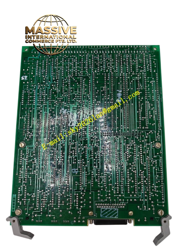
Description
GE DS200IMCPG1BCA
Technical Specifications
- Part Number: DS200IMCPG1BCA
- Product Type: Drive Interface / Motor Control Board
- System Compatibility: GE Industrial Drives and Motor Controllers
- Signal Type: Analog and Digital Control Signals
Functional Features
- Signal Translation: Converts digital control logic into analog drive signals for motor speed and torque regulation.
- Feedback Processing: Handles encoder and resolver feedback to ensure precise closed-loop motor control.
- Fault Monitoring: Continuously monitors motor current and voltage, triggering protective shutdowns during anomalies.
Application Scenarios
Variable frequency drives (VFDs), servo motor control systems, and heavy industrial manufacturing machinery.
Performance Parameters
- Response Time: Millisecond-level processing for real-time motion control.
- Signal Accuracy: High-resolution analog processing for smooth motor operation.
Material Composition
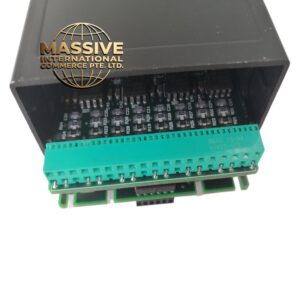
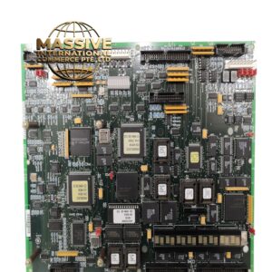
Industrial-grade PCB populated with precision operational amplifiers, optical isolators, and high-speed digital logic ICs.
Structural Characteristics
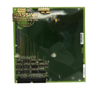
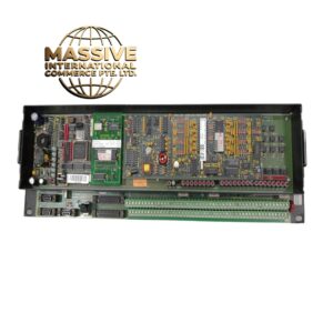
Standard drive card form factor with multi-pin backplane connectors and front-panel diagnostic test points.
Working Principle
Receives speed and torque setpoints from the master controller, compares them with actual motor feedback, and adjusts the PWM output to the power stage to maintain precise motor regulation.
Installation Requirements
- Install in the designated control slot within the drive chassis.
- Verify all ribbon cables and signal harnesses are securely seated.
- Configure hardware jumpers according to the specific motor application.
Usage Precautions
- Strictly observe Electrostatic Discharge (ESD) protocols.
- Never insert or remove the board while the drive control power is active.
- Ensure proper grounding to prevent electromagnetic interference.