Description
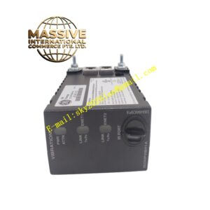
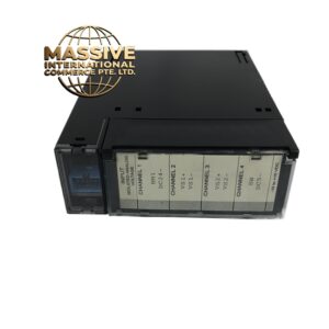
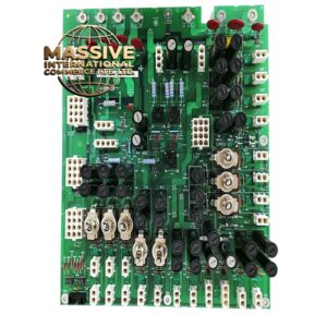
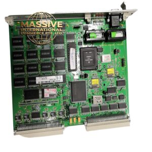
GE RMIO-LGGGXXXXX
- Technical Specifications (Typical for GE RMIO):
- Supply Voltage: 24 V DC nominal
- I/O Types: Mixed digital inputs/outputs, analog inputs, encoder interfaces
- Communication: Fiber-optic or serial link to drive controller
- Mounting: DIN rail or drive cabinet panel
- Functional Features: Galvanic isolation between field I/O and controller; signal conditioning for encoder feedback; distributed I/O expansion; diagnostic LEDs for link status and channel faults; noise-immune fiber communication option.
- Application Scenarios: Variable frequency drive auxiliary control panels, remote station I/O for conveyor systems, motion control feedback aggregation, retrofitting legacy drive systems with modern I/O.
- Performance Parameters: Response time <1 ms for digital I/O; analog resolution 12–16 bit; operating temperature 0–60°C; protection class IP20 (chassis mounted).
- Material Composition: PCB with industrial-grade SMD components; plastic housing (UL94 V-0); gold-plated contacts on removable terminal blocks; optically isolated channels.
- Structural Features: Compact modular housing with top/bottom removable terminals; front-panel status LEDs; D-sub or RJ45 style communication ports; locking levers for DIN rail.
- Working Principle: Field sensors/actuators connect to the module’s terminals; signals are conditioned (filtered, isolated, converted to logic levels), packaged into data frames, and transmitted over a dedicated link to the main drive or PLC processor which executes control logic and returns output commands.
- Installation Requirements: Mount on 35 mm DIN rail with proper spacing for ventilation; separate high-voltage wiring from low-voltage signal cables; terminate shield drains to ground at one end only.
- Usage Precautions: Verify communication protocol selection via DIP switches if present; avoid bending fiber-optic cables sharply; ensure 24 V DC supply is isolated from noisy power sources; replace only with identical module revision to maintain firmware compatibility.