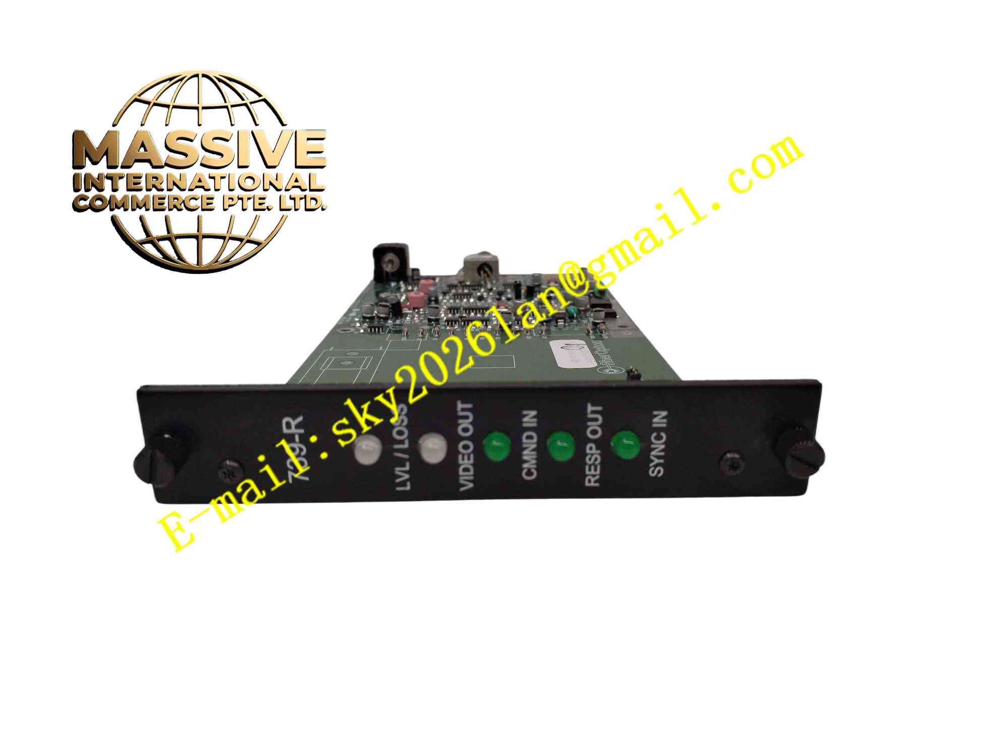
Description
GE S739DVR-RST1
Technical Specifications Brand: GE Model: S739DVR-RST1 Power Supply: 12 VDC, 150 mA typical Fiber Interface: LC duplex fiber port Video Input over Fiber: Composite analog video, 1 Vp-p 75 Ohm Video Output: BNC connector 75 Ohm composite video Serial Data: Bidirectional RS232/RS422/RS485 adaptive Signal Bandwidth: 10 Hz to 10 MHz Operating Temperature: -40°C to +75°C Storage Temperature: -40°C to +85°C Humidity: 5% to 95% non-condensing Protection Grade: IP20 Mounting: DIN rail or panel mounting
Functional Features Receive optical video signal and restore analog composite video output. Bidirectional transparent transmission of serial control data over fiber link. Built-in signal diagnostic circuit monitors optical power level. LED indicators show power status, optical link and data transmission activity. Adaptive serial interface automatically identifies RS232, RS422 and RS485 signal levels. High EMC immunity for industrial electromagnetic noise environment. Wide operating temperature range for harsh field deployment.
Application Scenarios Oil refinery remote video surveillance, railway trackside camera transmission, power substation long-distance video monitoring, offshore platform camera signal transmission, factory long distance security monitoring.
Performance Parameters Stable video reconstruction under low optical input power. Bidirectional serial data transmission without protocol modification. Fast detection of fiber break and optical power loss. Resist surge and common mode interference on electrical side. Maintain video quality over long fiber transmission distance.
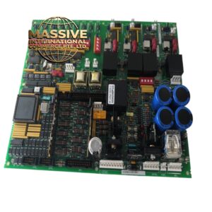
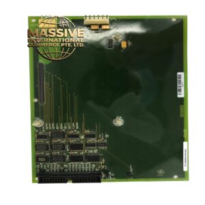
Material Composition Enclosure: Powder coated aluminum metal housing. PCB: FR4 multilayer industrial printed circuit board. Core Components: Optical receiver chip, video amplifier, serial transceiver chip, surge protection components. Connectors: LC fiber connector, BNC video connector, screw terminal block for serial and power. Indicator: SMD LED.
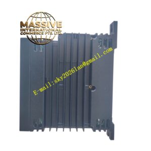
Structural Features Compact rectangular metal casing. Front panel arranges fiber port, BNC port and status LEDs. Rear side has screw terminal block for DC power and serial wiring. Internal metal shielding isolates optical circuit and electrical circuit. Mounting holes on housing for panel installation, compatible with DIN rail adapter.
Working Principle Optical fiber carries modulated video and serial data optical signal into LC port. Photodiode converts optical signal into electrical analog signal. Video amplifier recovers composite video and outputs to BNC connector. Serial data demodulation circuit extracts bidirectional control data and sends to terminal block as RS232/422/485 electrical signal. The module continuously measures received optical power and triggers link fault indicator when optical signal drops below threshold.
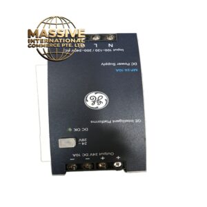
Installation Requirements Mount metal housing on solid panel or DIN rail. Use matching fiber patch cord and clean fiber end face before connection. Connect 12 VDC power supply to terminal block with correct polarity. Terminate serial wiring according to selected serial standard. Route fiber cable separately from high voltage power cables. Verify video image and serial communication after power on.
Usage Notes Do not look directly at active fiber laser port. Protect fiber connector from dust and scratches. Check DC power polarity strictly, reverse polarity damages circuit. Avoid bending fiber cable below minimum bend radius. Inspect optical link power reading periodically during maintenance.