



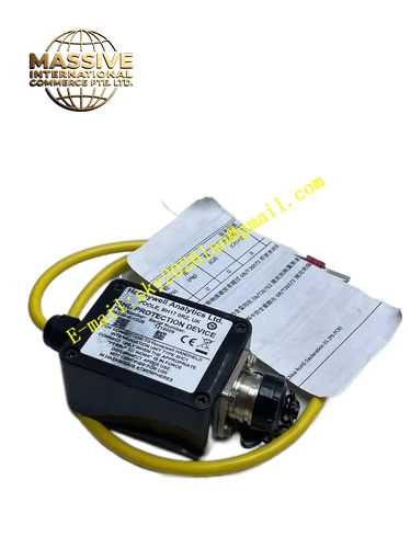
Description
Honeywell 04230-A-1025
Technical Specifications
- Compatible detectors: C7035 series UV flame detectors
- Input: UV sensor high-impedance input
- Output: SPDT dry contact, 3 A / 250 V AC
- Supply voltage: 120 V AC 50/60 Hz
- Maximum detector cable length: 100 meters
- Response time: ≤0.5 seconds
- Operating temperature: 0 °C to +60 °C
Functional Features High-gain amplifier compensates for signal loss over long detector cable runs. Input circuit impedance matched to long UV detector cables, minimizes signal reflection. Isolated output contact, blocks ground loop interference. On-board flame signal strength LED. Plug-in socket design, no rewiring required for module replacement. Fail-safe output state on internal circuit fault.
Application Scenarios Large boiler installations with remote flame detectors Long sight tube burner flame signal conditioning Replacement for 04230-A-1001 units with signal loss over long cables Legacy burner system upgrades requiring extended detector cable runs
Performance Parameters
- Input gain: 2 times the standard 04230-A-1001 amplifier
- Maximum cable compensation: 90% signal attenuation
- Contact rating: 3 A resistive
- Response time: ≤0.5 seconds
- Operating humidity: 10% to 90% non-condensing
Material Composition ABS plug-in housing High-gain differential amplifier circuit Input impedance matching network SPDT output relay Socket base Gold-plated module pins
Structural Features Small rectangular plug-in module. Front flame signal LED. Bottom gold-plated pins insert into the socket base. Input matching network located close to the input pins, minimizes cable signal pickup. Socket base mounts on DIN rail.
Working Principle The UV detector signal travels along the long cable to the amplifier input. The high-impedance differential amplifier receives the attenuated signal, amplifying it to trigger level. The matched input network prevents signal reflection at the cable input, maximizing received signal strength. When amplified UV signal confirms flame, the output relay closes, sending flame present signal to the burner control. On flame loss, the relay opens for safety shutdown. Internal fault forces the relay to open, defaulting to safe flameout state.
Installation Requirements Mount the socket base on the DIN rail near the burner control cabinet. Use shielded cable for detector wiring, single-point shield grounding. Plug the amplifier module into the socket. Adjust sensitivity, confirm flame signal remains stable over the full cable run.
Usage Notes Maximum detector cable length must not exceed 100 meters; longer runs cause signal noise. Shield drain wire grounded at the control end only, double-ended grounding causes ground loop hum. High-gain setting makes the circuit more sensitive to EMI; route detector cables away from power wiring. Replace the module immediately if flame signal LED flickers without real flame, this indicates amplifier degradation.







