



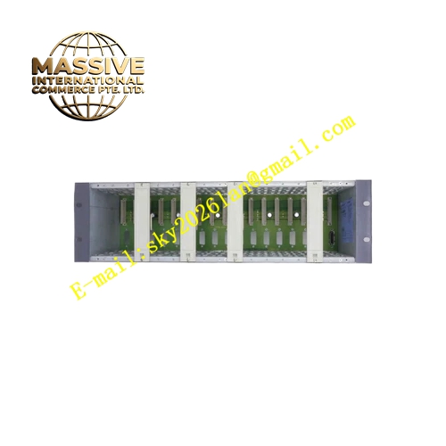
Description
Honeywell 05701-A-0511
Technical Specifications Power input 24VDC Operating current 130mA Compatible with Honeywell UV flame sensors Adjustable flame failure delay 0.2s to 4s Relay output rated 5A 240VAC Analog output signal range 4-20mA proportional to flame intensity Operating temperature -20℃ to 70℃ Storage temperature -40℃ to 85℃ Humidity 5% to 95% non-condensing Fault detection for probe open and short circuit
Functional Features It converts UV flame pulses into discrete flame present / flame loss relay signal. It generates 4-20mA analog output representing relative flame intensity. It supports adjustable flame failure timer to prevent nuisance trips. It outputs fault alarm when probe wiring is open or shorted. The analog signal can be sent to DCS for trend recording of flame quality. It provides local visual indication of flame and fault status via front panel LEDs.
Application Scenarios Combustion optimization monitoring for refinery process heaters Boiler flame intensity trending in thermal power plants Gas furnace flame quality monitoring in chemical synthesis units Incinerator combustion stability monitoring Burner performance monitoring for hot oil heating systems
Performance Parameters Analog output linearity error stays below ±2% of full scale Flame signal noise rejection ratio exceeds 38dB Relay action time is less than 20ms Analog signal update cycle is 100ms
Material Composition Circuit board uses FR4 flame retardant substrate with conformal coating Analog conversion components are high-stability precision chips Relay contacts use silver cadmium oxide alloy Housing is flame retardant ABS plastic Terminal blocks use heat-resistant nylon material
Structural Characteristics DIN rail mounted plastic enclosure Front panel has delay adjustment potentiometer and LED indicators for power, flame and fault Separate terminal groups for power supply, UV probe, relay contact and 4-20mA analog output Internal circuit assembly is designed to withstand burner vibration Enclosure protection grade IP20
Working Principle UV pulse signals from the flame detector enter the amplifier circuit. The signal conditioning circuit extracts valid flame pulses and calculates relative flame strength. The comparator triggers relay status change based on flame presence and preset delay. A dedicated D-A circuit converts flame intensity measurement into 4-20mA analog current signal. The diagnostic circuit monitors probe wiring integrity and activates fault output when wiring failure occurs.
Installation Requirements Install the module on standard 35mm DIN rail inside control cabinet Use shielded twisted pair for UV probe wiring and analog signal wiring Separate low-level signal cables from ignition high voltage wiring Terminals must be fastened to the required torque value Calibrate the 4-20mA output range during commissioning
Usage Notes The analog output reflects relative flame intensity and cannot be used for absolute radiant heat measurement Do not run analog signal cable together with high power AC cables Verify both relay function and analog output during commissioning test Clean UV probe window regularly to prevent reduced signal strength







