



Description
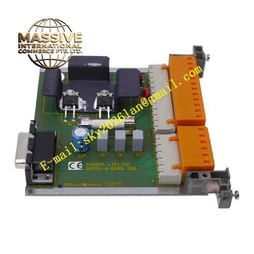
Honeywell 05701-A-0550
Technical Specifications Power supply 24VDC Operating current 140mA Compatible with Honeywell UV flame sensors Adjustable flame failure response time from 0.5s to 5s Relay contact rating 5A 240VAC Operating temperature -20℃ to 70℃ Storage temperature -40℃ to 85℃ Humidity 5% to 95% non-condensing Automatic sensor self-test cycle runs every several seconds
Functional Features It amplifies and discriminates UV flame pulse signals. It executes automatic on-line diagnostic test of the UV probe circuit without shutting down the burner. It distinguishes real flame loss from probe failure. It provides adjustable flame loss delay to accommodate flame turbulence. It outputs fault indication for failed self-test, open circuit or short circuit of the probe. It maintains flame relay status correctly during normal self-check cycles.
Application Scenarios Critical burner flame safety supervision for power plant auxiliary boilers Furnace flame monitoring for petrochemical process heaters High-risk gas burner interlock systems in chemical plants Hazardous waste incinerator flame detection Burner management for hydrogen-fueled heating systems
Performance Parameters Self-check sequence completes without false flame trip Noise rejection ratio is greater than 40dB Relay contact switching time is less than 20ms Diagnostic response to permanent probe fault is less than 500ms
Material Composition Main circuit board is FR4 flame retardant PCB with conformal coating Signal processing chips are industrial grade CMOS devices Output relay uses arc-resistant contact alloy Enclosure is flame retardant ABS plastic Terminal insulation material is glass-filled nylon
Structural Characteristics DIN rail mount plastic housing Front panel has adjustment potentiometer for flame failure delay, plus power, flame and fault LED indicators Screw terminals are arranged on the lower edge for power, probe signal and relay wiring Internal components are reinforced for vibration resistance Enclosure protection class IP20
Working Principle UV pulse signals from flame probe enter the amplifier. The filter and comparator circuit evaluate flame signal characteristics. At scheduled intervals, the internal self-test circuit applies test signals to the probe circuit and checks the response. If the probe circuit responds abnormally, the amplifier locks in fault status and activates fault alarm. If the probe passes self-test and flame pulses stop for longer than the set delay, flame loss relay action occurs.
Installation Requirements Mount on 35mm DIN rail inside control cabinet Use shielded twisted pair wire for UV probe wiring Isolate probe cable from ignition transformer high voltage leads Verify 24VDC polarity before energizing Complete full functional test with flame simulator after installation
Usage Notes The self-check function cannot test optical window contamination caused by soot Periodic physical inspection and cleaning of the UV probe window remain mandatory Adjust flame failure delay according to burner manufacturer specifications Do not bypass the fault contact in safety interlock loops







