



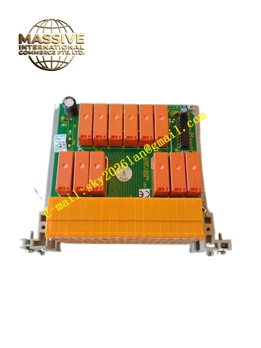
Description
Honeywell 05704-A-0121
Technical Specifications Supports analog 4-20mA and 0-10V setpoint input; supports dry contact digital interlock input; rated control power 24VDC; each signal channel equipped with RC filter and transient suppression components; operating temperature 0℃ to 60℃; storage temperature -40℃ to 85℃; relative humidity 5% to 95% non-condensing; rack-mounted small board structure; UL and CE certification.
Functional Features It concentrates external control and feedback signals to labeled screw terminals. It filters high-frequency interference noise on analog and digital control lines. It suppresses voltage surge introduced by field contact and sensor wiring. It transmits conditioned signals to the main drive control module through internal board-to-board connector. It provides channel status indication for each input point. It isolates external control circuit and drive main power circuit.
Application Scenarios Signal expansion interface for textile machine variable frequency drive; external interlock wiring base for printing machine drive unit; feedback signal collection board for plastic extruder speed control system.
Performance Parameters Analog signal transmission linearity error meets drive control precision requirement; digital signal response delay will not affect drive real-time adjustment; terminal contact resistance stays stable under cabinet vibration.
Material Composition Circuit substrate is FR4 flame-retardant PCB with conformal coating; terminal conductive parts are tin-plated copper alloy; filter resistors and capacitors are high-precision industrial grade; signal isolation components are optocoupler chips; board fixing bracket is cold rolled steel with anti-rust coating.
Structural Characteristics Small rectangular plug-in auxiliary board; front side printed with channel function labels and screw terminals; rear integrated board-to-board connector for mating with main drive module; fool-proof keying structure to prevent reverse insertion; reserved mounting holes for screw fixing.
Working Principle External speed setpoint analog signal and safety interlock contact signal connect to the terminal blocks of 05704-A-0121. Signals pass through surge suppression and passive filtering circuits, and are isolated by optocoupler devices. Processed digital and analog information is transmitted to the main drive control module for speed and interlock logic calculation. This board only completes signal conditioning and transmission and does not carry power conversion function.
Installation Requirements Insert the auxiliary board into the reserved slot of matched drive module and lock the fixing screws. Separate low-voltage control signal cables and high-current power cables. Tighten all field terminal screws to specified torque. Ensure reliable single-point grounding of the drive cabinet.
Usage Notes Do not connect high-voltage power signal to control terminals. Verify signal polarity and wiring definition before power supply. Wear anti-static wrist strap during board disassembly and replacement. Regularly clean terminal dust to avoid poor contact.







