



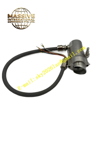
Description
Honeywell 2104B6250
Technical Specifications
- Detection principle: Photoelectric light scattering
- Supply voltage: 24 V DC from fire alarm panel
- Alarm output: Form C relay contact, 2 A / 30 V DC
- Sensitivity: 0.05 to 0.20 dB/m adjustable
- Operating temperature: 0 °C to +50 °C
- Duct air velocity: 1.5 to 10 m/s
- Mounting: Sheet metal duct mount
Functional Features Sampling tube draws duct air into the sensing chamber, detects smoke even at low air volumes. Remote test indicator, allows alarm verification without climbing into the duct. Field-adjustable sensitivity, optimized for different duct airflow conditions. Automatic drift compensation, accounts for dust buildup in the sensing chamber. Alarm and trouble contact outputs, integrates directly with building fire alarm panels. Tamper-resistant cover, prevents unauthorized access to the sensing chamber.
Application Scenarios Commercial building HVAC duct smoke detection Hospital and school supply duct fire alarm integration Underground parking garage ventilation smoke monitoring Retrofit replacement for legacy duct smoke detectors
Performance Parameters
- Alarm response time: ≤20 seconds after smoke entry
- Chamber dust tolerance: Compensation for 10 mg/m² accumulated dust
- Relay contact life: 100,000 operations
- Operating humidity: 10% to 95% non-condensing
- Sampling tube length: 1 meter standard, extends to 3 meters maximum
Material Composition ABS flame retardant detector housing Photoelectric LED and photodiode chamber Aluminum sampling tube Brass duct mounting collar Stainless steel mounting screws Silicone chamber seal
Structural Features Rectangular plastic detector housing. Round duct mounting collar on the bottom. Aluminum sampling tube extends across the duct interior. Remote test LED on the housing side. Screw terminal block for power and alarm wiring.
Working Principle HVAC duct airflow pushes air through the sampling tube, entering the detector sensing chamber. In normal clean air conditions, the chamber LED emits light that misses the photodiode, no alarm signal. When smoke enters the chamber, smoke particles scatter LED light onto the photodiode. The photodiode detects scattered light intensity; when signal exceeds the set sensitivity threshold, the internal relay actuates, sending an alarm signal to the fire alarm panel. The drift compensation circuit adjusts sensitivity as dust accumulates, preventing false alarms from chamber fouling.
Installation Requirements Mount the detector on the duct sidewall, drill a matching mounting hole. Insert the sampling tube across the full duct width, secure with the mounting collar. Connect 24 V DC supply and alarm relay contacts to the fire alarm panel. After power-up, perform a test smoke entry, verify alarm relay triggers. Set sensitivity per duct airflow velocity.
Usage Notes Sampling tube openings must not face directly into airflow, this creates pressure bias on the sample. Clean the sensing chamber annually, dust buildup causes false alarms. Never paint the detector housing or sampling tube, this blocks sample air flow. Do not install the detector within 1 meter of HVAC coil condensate drains, water droplets enter the chamber.







