



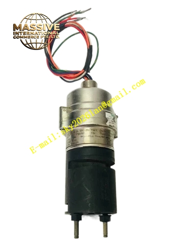
Description
Honeywell 2108B2001N
Technical Specifications
- Detection principle: Photooelectric light scattering
- Supply voltage: 15 to 32 V DC from addressable fire loop
- Communication: Addressable SLC loop
- Sensitivity: 0.09 to 0.19 dB/m
- Operating temperature: 10 °C to +32 °C
- Mounting: Standard 4-inch ceiling base
- Base compatibility: Honeywell addressable detector bases
Functional Features Addressable design, each detector has a unique loop address, reports exact alarm location. Low-profile ceiling mount, unobtrusive in finished interiors. Automatic sensitivity drift compensation, adjusts for chamber dust aging. Remote test LED visible from below, allows alarm verification from floor level. Isolator circuit on the loop, prevents single detector short circuit from disabling the entire loop. Test magnet activation, no removal required for functional testing.
Application Scenarios Commercial office building ceiling smoke detection Hotel corridor and guest room fire alarm installation Retail shop open area smoke monitoring New construction addressable fire alarm system integration
Performance Parameters
- Alarm response time: ≤10 seconds after smoke entry
- Loop current: 200 μA standby, 2 mA alarm
- Detector diameter: 102 mm, height 40 mm
- Operating humidity: 10% to 95% non-condensing
- Loop address set via DIP switches on the base
Material Composition White ABS plastic housing Photoelectric sensing chamber Infrared LED emitter Silicon photodiode receiver Stainless steel mounting base Metal contact springs
Structural Features Round low-profile white plastic housing. Side entry air vents around the chamber. Bottom twist-lock mount on the addressable base. Test LED lens visible through the housing cover. DIP switches on the base set detector address.
Working Principle Ambient air enters the sensing chamber through side vents. In clean air, the IR LED beam does not reach the photodiode. When smoke particles enter the chamber, they scatter LED light onto the photodiode. Signal intensity rises as smoke density increases; when it crosses the alarm threshold, the detector communicates its address to the fire panel via the SLC loop, triggering location-specific alarm. The isolator circuit disconnects the loop segment downstream when a short circuit occurs, isolating the fault without disabling remaining detectors.
Installation Requirements Mount the addressable base to the 4-inch ceiling electrical box. Set unique detector address via base DIP switches. Twist the detector onto the base until it locks. After loop power-up, run panel device detection, confirm the detector registers correctly. Perform test magnet smoke test, verify alarm transmission.
Usage Notes Detector spacing must follow local fire code, maximum spacing 9 meters between detectors. Never paint the detector cover, paint blocks air entry to the chamber. Install detectors at least 0.5 meters away from supply air diffusers, this dilutes smoke samples. Clean the sensing chamber every 5 years in dusty environments.







