



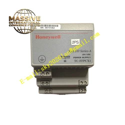
Description
Honeywell 248-627-3135
Technical Specifications
- Compatible devices: UDC2500, UDC3200 series digital temperature controllers
- Communication interface: RS485 half-duplex
- Communication rate: 1200–19200 bps configurable
- Communication protocol: Modbus RTU
- Supply power: Drawn from the controller expansion slot, no external power required
- Isolation withstand voltage: 1500 VAC optocoupler isolation
- Operating temperature: 0 °C to +60 °C
Functional Features Plug-and-play operation, adds communication function immediately after insertion into the controller expansion slot. Supports upper system reading of temperature measured value, setpoint, output percentage and alarm status. Supports remote temperature setpoint modification and auto/manual mode switching from upper system. On-board optocoupler isolation, blocks common-mode interference on communication lines. On-board LEDs indicate transmit and receive communication activity. Bus node address configured via controller front panel buttons.
Application Scenarios Connection between standalone temperature controllers and workshop SCADA systems Remote monitoring for reactor and furnace temperature Networked centralized monitoring for multiple temperature controllers Upgrade retrofit for old controllers without communication ports
Performance Parameters
- Communication distance: 1200 meters shielded twisted pair
- Isolation withstand voltage: 1500 VAC for 1 minute
- Communication response time: ≤100 ms
- Maximum bus node count: 32 temperature controllers
- ESD protection: ±8 kV contact discharge
Material Composition FR4 PCB substrate RS485 transceiver chip Optocoupler isolation device Gold-plated expansion slot connector RS485 screw terminals ABS flame retardant enclosure
Structural Features Small long rectangular module, clips to the controller side expansion slot. Rear gold-pin connector mates to the controller expansion interface. Front screw terminals route A and B communication wires and ground. Front panel two LEDs indicate TX and RX communication activity.
Working Principle After inserting into the controller expansion slot, internal pins establish a data channel with the controller CPU. Modbus commands sent from the upper system over RS485 enter the module, pass through level conversion and optocoupler isolation to the controller CPU; controller response data passes through the module and converts back to RS485 signals for transmission to the upper system. Optocoupler isolation blocks common-mode interference between communication lines and controller power. LEDs indicate signal activity during data transmit and receive.
Installation Requirements Insert the module into the controller expansion slot only when power is off, press pins fully seated. Terminate RS485 communication wires A and B to corresponding terminals, never reverse polarity. Parallel a 120 Ω termination resistor at the bus far end. After power-up, set communication address, baud rate and parity in the controller menu.
Usage Notes Reversed A/B wiring causes communication failure; verify wiring polarity during troubleshooting. Bus node addresses must not be duplicated; address collision causes communication failure for all devices. Hot-swapping the module during operation causes controller CPU reset; perform parameter modifications with power off. Shield layer single-point grounding prevents ground loop interference.







