



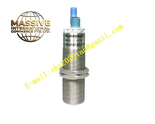
Description
Honeywell 2MLF-RD4A
Technical Specifications
- Channel count: 4 RTD input channels
- Supported sensors: Pt100, Pt1000, Ni100
- Connection types: 2-wire, 3-wire, 4-wire
- Resolution: 16-bit ADC
- Backplane interface: MasterLogic 200 expansion bus
- Operating temperature: 0 °C to +55 °C
Functional Features 3-wire and 4-wire lead resistance compensation, eliminates measurement error from long RTD cables. 16-bit high-resolution ADC, delivers 0.1 °C measurement accuracy. Open sensor detection, triggers channel fault when RTD element breaks. Per-channel digital filter smooths temperature signal. Module status LED indicates power and fault. Configuration via PLC programming software.
Application Scenarios MasterLogic 200 high-precision temperature monitoring Reactor and furnace temperature measurement HVAC chilled water temperature sensing Spare part replacement for failed RTD input modules
Performance Parameters
- Measurement accuracy: ±0.1 °C over -200 °C to +850 °C range
- Lead resistance compensation: Up to 50 Ω per lead
- Update rate: 50 ms per channel
- Open sensor detection response: ≤200 ms
- Temperature drift: ±10 ppm/°C
Material Composition ABS flame retardant housing 16-bit ADC chip Precision current source for RTD excitation Platinum reference resistor Removable screw terminal block Gold-plated backplane connector
Structural Features Narrow rectangular DIN-rail mount housing. Front removable terminal block labeled per RTD channel. Side expansion bus connector. Front power and fault LEDs. DIN rail mounting clip.
Working Principle The module supplies a precision constant current through the connected RTD sensor. Current flow across the RTD element produces a voltage proportional to element resistance. The 16-bit ADC measures this voltage, converting to temperature value using the RTD resistance-temperature curve. 3-wire and 4-wire configurations measure lead resistance separately, subtracting lead voltage drop from the measurement. Open sensor detection monitors excitation current; no current flow indicates a broken RTD element, triggering a channel fault flag.
Installation Requirements Clip the module to the DIN rail. Connect RTD sensors using 3-wire or 4-wire shielded cable. Configure sensor type and wire count in PLC software. Verify measured temperature matches a calibrated reference sensor after power-up.
Usage Notes RTD wiring must use shielded cable, routed away from high-voltage cables. 2-wire RTD connections are only acceptable for short cable runs; long runs require 3-wire compensation. Never apply 24 V power to RTD input terminals, this destroys the excitation circuit. Individual channel groups must not be mixed with voltage inputs; RTD channels supply excitation current







