



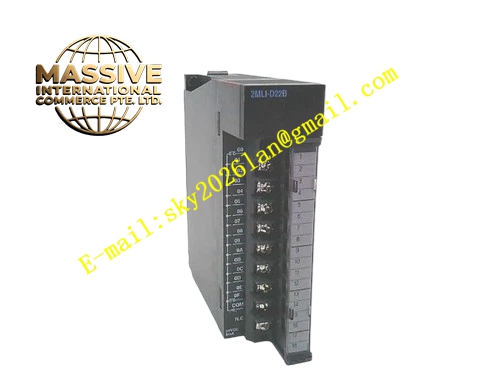
Description
Honeywell 2MLL-C42B
Technical Specifications
- Communication ports: 2 isolated RS485 ports
- Protocol: Modbus RTU master/slave
- Isolation: 500 VAC between ports
- Backplane interface: MasterLogic 200 expansion bus
- Supply power: 5 V DC from backplane
- Operating temperature: 0 °C to +55 °C
Functional Features Dual isolated RS485 ports, independent baud rate and address configuration per port. Supports both Modbus master and slave operation on each port. On-board LEDs indicate port communication activity and fault status. Hot swap support, module replacement without full PLC shutdown. Configurable via PLC programming software. Galvanic isolation between ports, prevents ground loop interference.
Application Scenarios PLC connection to separate HMI and VFD networks Plant Modbus network integration for MasterLogic systems Expansion for PLC systems requiring additional serial communication Spare part replacement for failed communication modules
Performance Parameters
- Maximum baud rate: 115200 bps per port
- Isolation withstand voltage: 500 VAC for 1 minute
- Maximum bus node count: 32 devices per port
- Bus distance: 1200 meters at 9600 bps
- ESD protection: ±8 kV contact discharge
Material Composition ABS flame retardant housing RS485 transceiver chips Optocoupler isolation devices Removable screw terminal block Gold-plated backplane connector DIN rail mounting clip
Structural Features Narrow rectangular DIN-rail mount housing. Front removable terminal block for both port A and port B wiring. Side expansion bus connector. Front port activity LEDs. DIN rail mounting clip.
Working Principle The module receives Modbus data frames from the CPU over the expansion bus. Each port transceiver converts data to RS485 electrical signals for transmission to connected devices. Inbound data from the bus passes through optocoupler isolation, packaged and sent to the CPU over the backplane. Each port operates independently, allowing separate network segments with different baud rates and device addresses. LEDs indicate transmit and receive activity on each port.
Installation Requirements Clip the module to the DIN rail on the expansion bus. Connect RS485 devices to port A and port B terminals. Enable 120 Ω termination resistors at the far end of each bus segment. Configure baud rate and protocol in PLC software. Verify both ports communicate correctly after power-up.
Usage Notes RS485 A and B wiring must not be reversed; reversed wiring causes no communication. Never connect ground lines between separate isolated buses, this breaks isolation. Exceeding 32 devices per port requires an repeater. Port wiring routed near high-voltage cables causes communication errors.







