



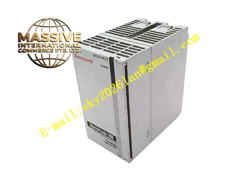
Description
Honeywell 2MLR-DBDF
Technical Specifications
- Digital input channels: 8, 24 V DC sink/source
- Digital output channels: 8, 24 V DC, 0.5 A per channel
- Backplane interface: MasterLogic 200 expansion bus
- Isolation: 500 VAC between field side and backplane
- Supply power: 24 V DC field power
- Operating temperature: 0 °C to +55 °C
Functional Features Integrated 8 input and 8 output channels on one narrow module. Per-channel LED indicators show input state and output state. Per-channel output short-circuit protection. Input debounce time configurable per channel. Hot swap support. Removable terminal block simplifies field wiring.
Application Scenarios Compact machine control I/O expansion Small conveyor system discrete signal collection and actuation Machine tool limit switch and solenoid valve interface Spare part replacement for combined I/O module faults
Performance Parameters
- Input threshold: 15 V DC minimum ON, 5 V DC maximum OFF
- Output current: 0.5 A per channel, total 4 A per module
- Input response time: ≤1 ms, debounce adjustable
- Output short circuit protection: 0.6 A current limit
- Isolation withstand voltage: 500 VAC for 1 minute
Material Composition ABS flame retardant housing Optocoupler input isolator array Power transistor output array TVS protection diodes Removable screw terminal block Gold-plated backplane connector
Structural Features Narrow rectangular DIN-rail mount housing. Front removable terminal block, upper row for inputs, lower row for outputs. Per-channel LEDs for input and output status. Side expansion bus connector. DIN rail mounting clip.
Working Principle Field 24 V DC switch signals connect to input channels, routed through optocouplers to the PLC logic. Isolated digital levels indicate input contact state, read by the CPU during scan cycles. CPU output commands travel over the backplane to the module, driving power transistors on output channels to switch 24 V DC loads. Short circuit protection limits output current on overcurrent faults. Per-channel LEDs display real-time input and output states.
Installation Requirements Clip the module to the DIN rail on the expansion bus. Wire field switches to input terminals, solenoid loads to output terminals. Connect 24 V DC field supply. Configure input debounce and output fail-safe values in PLC software. Verify channel operation during commissioning.
Usage Notes Total module output current must not exceed 4 A, overloading triggers module over-temperature. Inductive loads require flyback diodes across coil terminals. Never connect AC power to 24 V DC input terminals, this destroys optocouplers. Removable terminal blocks must be fully seated to maintain contact reliability.







