



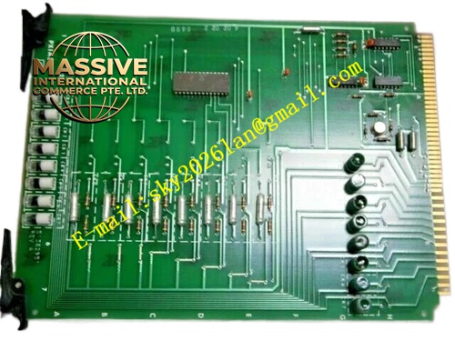
Description
Honeywell 4DP7APX1A322F
Technical Specifications
- Input Signal: 4 mA to 20 mA DC analog current
- Channel Count: 32 input channels
- A/D Converter Resolution: 16 bit sigma-delta ADC
- Input Shunt Impedance: 250 Ω precision internal shunt
- Channel Isolation: Group-wise reinforced isolation, 500 VAC isolation rating
- Backplane Interface: Honeywell proprietary DCS parallel backplane bus
- Operating Temperature: 0 °C to +60 °C
- Update Rate: Configurable group scan rate
- Power Consumption: 8 W maximum
Functional Features Under-range and over-range detection identifies transmitter fault and process signal out-of-limit condition. Open loop detection triggers fault alarm when field wiring breaks. Digital low pass filter with configurable time constant suppresses high frequency measurement noise. Dual sampling comparison logic improves measurement integrity for critical process loops. Front panel LED indicators show module power, group fault and channel fault status. All data communication frames carry CRC checksum for error detection.
Application Scenarios Refinery and chemical plant pressure, temperature, flow and level transmitter signal collection Continuous DCS control loop analog input expansion Power plant boiler auxiliary process variable monitoring Legacy Honeywell DCS system overhaul spare replacement
Performance Parameters
- Measurement Accuracy: ±0.1 % full scale
- Zero temperature drift: Less than 25 ppm per degree Celsius
- Channel crosstalk: -65 dB minimum
- Fault detection response time: Less than 120 ms for open loop fault
- Sampling synchronization across all channels
Material Composition High TG FR4 multilayer PCB, precision metal film shunt resistors, sigma-delta ADC integrated circuits, reinforced optocoupler isolators, instrumentation amplifiers, decoupling ceramic capacitors, tin plated screw terminal block, flame retardant plastic module housing, gold plated edge connector for backplane.
Structural Features Standard plug-in DCS rack card form factor. Removable split terminal block for field transmitter wiring. Front panel LED array for status indication. Internal isolation barrier divides field analog circuit area and rack logic bus area. Card edge anti-reverse keying feature prevents wrong orientation insertion. Component layout optimizes signal trace length matching to reduce crosstalk.
Working Principle Field 4-20mA current passes through precision internal shunt resistor and converts to proportional voltage signal. Instrument amplifier amplifies and conditions voltage before feeding to dual independent ADC converters. Local logic chip compares two conversion results. If deviation stays within tolerance band, valid measurement value is packed into CRC protected bus frame and uploaded to controller. Deviation beyond threshold or current outside valid window triggers fault flag.
Installation Requirements Field transmitter wiring must be twisted shielded pair cable, shield grounded only at cabinet end. Separate analog signal cable from high voltage power cable in cable tray. Perform zero and span calibration after card replacement for safety related measurement loops. Confirm firmware compatibility with host DCS controller before commissioning. Tighten terminal screws to specified torque value.
Usage Notes Do not apply voltage signal directly to current input terminals. Do not ground shield at both transmitter and cabinet terminals. Filter time constant setting must match process dynamic response requirement. Bypassing dual ADC comparison diagnostic circuit is prohibited.







