



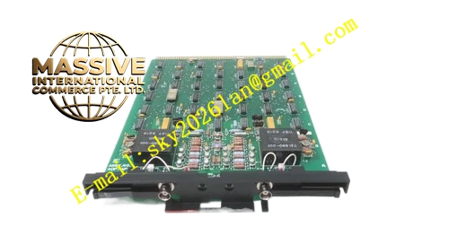
Description
Honeywell 4DP7APXDHIII
Technical Specifications
- Channel Count: High density multi-group digital input channels
- Input Type: 24 VDC wet sensing / dry contact compatible
- Group Isolation: 500 VAC reinforced isolation per group
- Backplane Bus: Proprietary DCS parallel backplane
- Operating Temperature: 0 °C to +60 °C
- Power Consumption: 6.8 W maximum
- Input Wetting Current: Limited constant current source per channel
Functional Features Per channel reverse polarity and overvoltage protection. Open and short circuit wiring fault diagnosis. Contact bounce suppression via configurable digital filter. Front panel LED status indicator for each group and module fault. CRC checksum validation for backplane communication frames. Input status hold during temporary backplane communication interruption.
Application Scenarios Valve position feedback signal acquisition for process control valves Conveyor and machinery limit switch status collection Pump and fan auxiliary contact feedback monitoring DCS interlock discrete input expansion
Performance Parameters
- Input sampling interval: 50 ms base scan rate
- Filter delay range: 5 ms to 400 ms configurable
- Insulation resistance: >1000 MΩ at 500 VDC
- Fault reporting speed: <100 ms
Material Composition FR4 multilayer PCB, optocoupler isolators, current limiting resistors, TVS surge diodes, ceramic decoupling capacitors, screw terminal block, flame retardant plastic housing, gold plated edge connector.
Structural Features Standard plug-in rack card form factor. Removable front terminal block for field contact wiring. Front panel LED array for group status and fault display. Internal isolation barrier between field input circuit and rack logic circuit. Anti-reverse insertion keying tab.
Working Principle Internal limited current wetting source applies sensing current to each input loop. Field contact closure changes loop impedance and optocoupler state. Logic chip debounces input signal and packs status data into communication frame. Frame is sent to DCS controller. Abnormal loop impedance triggers wiring fault flag.
Installation Requirements Field wiring adopts twisted pair and separates from analog and power cables. Dry contact devices must not carry external voltage. Set filter time to match mechanical bounce characteristic of field switches. Tighten terminal screws to specified torque.
Usage Notes External voltage injection to input terminals causes permanent card damage. AC signal cannot connect to this DC digital input card. Fault clearing requires correction of field wiring before system reset.







