



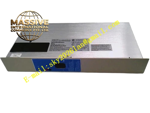
Description
Honeywell 51195156-100
Technical Specifications
- Memory Type: Static RAM
- Memory Capacity: 1MB
- Bus Interface: TDC3000 dedicated high-speed memory bus
- Power Supply: 5VDC from processor backplane
- Operating Ambient Temperature: 0°C to +60°C
- Storage Temperature: -40°C to +85°C
- Relative Humidity: 5% to 90% RH non-condensing
- Mounting Type: Plug-in slot installation on TDC3000 processor rack
- Certification: UL, CE, RoHS
- Parity Mode: Byte parity check
Functional Features It stores downloaded control strategy, point configuration, alarm limit and PID tuning parameters. It receives address, read and write commands from memory interface board. It executes data storage and output operation under strict timing control. It generates parity bit automatically during write operation and verifies parity bit during read operation. It triggers parity fault signal immediately when single bit error is detected. It carries front panel LED indicators for power, bus active and parity fault. It supports hot swap replacement in redundant processor rack configuration. It retains stored data during normal power hold-up cycle. It uploads parity error count and fault timestamp to TDC3000 operator station.
Application Scenarios TDC3000 redundant main processor rack memory storage Petrochemical plant critical reactor control node memory module Refinery cracking furnace safety control processor memory board Power plant boiler combustion control processor memory rack Chemical plant high-availability continuous process control node
Performance Parameters
- Memory Access Time: Less than 18ns
- Mean Time Between Failures: 820000 hours
- Parity Error Detection Rate: 100% for single bit error
- ESD Immunity: 8kV contact discharge
- Data Retention During Power Hold-up: Minimum 20ms
Material Composition FR4 flame retardant conformal coated multilayer PCB High-speed static RAM chip array Parity generation and checking logic chip Address buffer and data bus driving chip Gold plated edge connector for TDC3000 processor backplane Metal front panel with extraction handle and LED indicators Controlled impedance signal traces for high-speed memory bus
Structural Features Standard TDC3000 paddle card form factor. Front panel integrates grouped LED status indicators and extraction handle. Rear gold plated edge connector mates with dedicated memory bus on processor backplane. Memory chips are arranged symmetrically to match trace length and synchronous timing requirement. Anti-key notch prevents reverse insertion into rack slot. Locking clip secures module firmly after installation. Conformal coating fully covers PCB surface to resist industrial cabinet moisture and dust. High-speed signal traces adopt controlled impedance design to guarantee signal integrity.
Working Principle After receiving 5VDC power supply from processor backplane, the module completes power-on self-test and memory initialization. When the main processor sends write command, address bus selects target memory cell, data bus transmits data, parity logic generates parity bit and stores together with data. When read command arrives, stored data and parity bit are fetched simultaneously. Parity circuit compares calculated parity with stored parity bit. If mismatch is detected, parity fault flag generates and alarm message uploads to operator station.
Installation Requirements Wear anti-static wrist strap before inserting module into dedicated memory slot of processor rack. Lock extraction handle after alignment. Confirm matching with corresponding memory interface board hardware version. Power on rack and verify bus active LED steady on. Download control logic program from engineering workstation to verify normal program loading. Run long-time continuous test to confirm no parity error alarm.
Usage Notes This module must match the hardware version of supporting memory interface board. Do not remove module while redundant control node is running critical control loops. Do not touch memory chip pins directly. Replace module when continuous parity error alarm occurs and memory interface board is verified normal. Keep cabinet temperature stable to guarantee memory access timing accuracy.







