



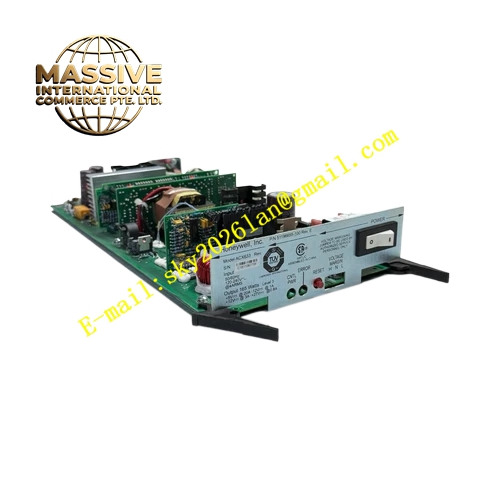
Description
Honeywell 51196655-100
Technical Specifications
- Input Voltage: 120 VAC to 240 VAC
- Input Frequency: 50 Hz / 60 Hz
- Max Input Current: 4 A
- Total Rated Output Power: 165 W
- Output Rails: +5 VDC @ 20 A, +12 VDC @ 3 A, +27 VDC @ 1 A, auxiliary rail @ 0.6 A
- Isolation Rating: Reinforced isolation between AC input side and DC output side
- Operating Temperature: 0 °C to +60 °C
- Storage Temperature: -40 °C to +85 °C
- Relative Humidity: 5 % to 95 % non-condensing
- Mounting Form: Plug-in rack mount module for LCN node chassis
- Cooling Method: Forced air internal fan cooling
Functional Features Multi-rail synchronized regulation maintains tight tolerance on all output voltages under dynamic load fluctuation. Built-in overvoltage, overcurrent and overtemperature protection shuts down output to prevent downstream board damage. Internal fault monitoring circuit captures fan failure, voltage deviation and input loss, and sends fault signal to node diagnostic register. Redundancy compatible design supports dual power feed configuration for critical control nodes. Front panel LED indicators display AC present, DC healthy and fault status separately. Soft-start circuit suppresses inrush current during power-up sequence to protect upstream distribution breakers.
Application Scenarios Honeywell TPS LCN node controller power source replacement Experion PKS legacy dual redundant control node maintenance retrofit Petrochemical plant DCS annual overhaul spare inventory Refinery, chemical and power station process control system emergency spare
Performance Parameters
- Voltage Regulation Accuracy: ±1 % across full load range
- Ripple and Noise: Less than 50 mV peak-to-peak on +5 V rail
- Overvoltage Protection Threshold: 5.7 V for 5 V rail, 14 V for 12 V rail
- Hold-up Time: Minimum 20 ms at full rated load after AC loss
- Fan Service Life: 50,000 hours at 40 °C ambient
- Fault response speed: Less than 100 µs for overvoltage shutdown
Material Composition Main housing: Cold rolled steel chassis with black powder anti-corrosion coating Power transformer: Laminated silicon steel core with copper winding and class B insulation Power switching semiconductors: IGBT and fast recovery rectifier diodes Control PCB: High TG FR4 UL94 V0 flame retardant substrate Cooling fan: Brushless DC fan with ball bearing assembly Filter components: Electrolytic bulk capacitors, ferrite EMI suppression beads, X and Y safety capacitors Terminal connector: Tin plated copper alloy power terminals
Structural Features Rectangular enclosed metal chassis designed for vertical insertion into LCN node rack. Front panel integrates status LED array and power fault signal connector. Internal layout segregates high voltage AC compartment and low voltage DC compartment by metal shielding barrier. Removable side cover allows internal component inspection during repair. Card edge locking tab prevents loose seating under continuous vibration. Internal wiring harness uses high temperature rated wire with crimped terminals.
Working Principle AC mains input passes through EMI filter and inrush limiting circuit before feeding high frequency switching inverter stage. High frequency transformer galvanically isolates primary AC side and secondary DC side. Multiple secondary windings feed independent synchronous rectifier and feedback regulation loops for each DC rail. Voltage sampling circuits continuously compare output voltage against reference band. Protection circuits trigger immediate shutdown once any electrical parameter exceeds factory calibrated threshold. Fan speed is controlled by internal temperature sensor.
Installation Requirements Fully power down node chassis and lock out upstream AC breaker before module replacement. Align module guide rails and push module until locking latch clicks into fixed position. Confirm wiring torque of AC input terminals matches manufacturer specification. Maintain unobstructed front-to-back airflow path through module cooling vents. Verify output rail voltage reading via diagnostic menu after power restoration. Separate AC input wiring from low voltage LCN communication cables.
Usage Notes Do not operate this unit without attached chassis fan assembly. Do not adjust internal potentiometers which are calibrated at factory. Do not run module outside the specified AC input voltage window. Replace fan assembly immediately upon fan fault alarm to avoid thermal shutdown. Handle with anti-static wristband when opening chassis cover.







