



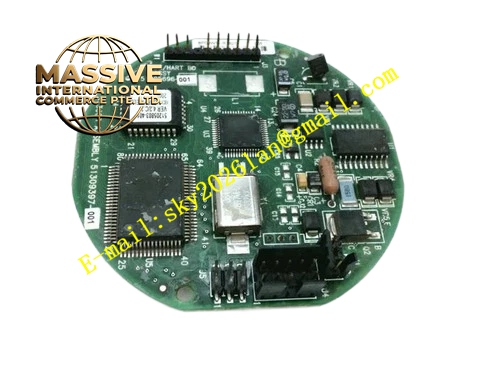
Description
Honeywell 51196694-901
Technical Specifications
- Network type: TPS LCN redundant high-speed control network
- Communication rate: 5 Mbps
- Interface ports: Dual coax BNC ports for A/B redundant networks
- Backplane interface: TPS operator station VME bus
- Supply power: 5 V DC from station backplane
- Operating temperature: 0 °C to +60 °C
- Isolation withstand voltage: 1500 VAC for 1 minute
- Hot swap support: Online replacement for faulty interface boards
Functional Features Dual redundant LCN network connection, automatic switchover to backup network on primary link failure. On-board signal shaping circuit compensates for signal attenuation over long network cable runs. Real-time network fault diagnosis, triggers station communication alarm on link loss. On-board LEDs indicate A network, B network link status and communication activity. Per-frame CRC verification for all transmitted data, transmission bit error rate below 10^-12. Supports network node address configuration via station software.
Application Scenarios Operator station to LCN network connection for TPS systems Spare part replacement for communication dropout faults in legacy LCN interface boards Network assembly for new TPS operator stations Communication upgrade for aging operator station network links
Performance Parameters
- Network switchover time: ≤1 ms
- Communication latency: ≤100 μs
- Maximum cable transmission distance: 300 meters RG6 coax
- Fault detection response: ≤50 ms
- Mean time between failures: 600,000 hours
Material Composition FR4 high-speed PCB substrate LCN network controller chip High-speed differential transceiver Gold-plated BNC coaxial connectors Optocoupler isolation devices Metal shielded front panel
Structural Features Standard VME form factor board. Front panel houses dual BNC network interfaces. LED array displays dual network communication status. Metal shielded enclosure contains high-speed bus electromagnetic radiation. Impedance-controlled 75 Ω trace layout matches coaxial cable characteristic impedance.
Working Principle After insertion into the operator station backplane, the board initializes LCN communication logic, establishing a data channel with the station main processor. Process data and alarm information to be uploaded travels from the station processor to the board, packaged into network frames and transmitted over the dual redundant coax links. Operator commands and configuration data from the LCN network return over the links to the board, forwarded to the station processor for execution. The link monitoring circuit continuously checks signal quality on both networks; when the active link is abnormal, automatic switchover to the backup network occurs.
Installation Requirements Insert the board into the dedicated LCN interface slot only when station power is off, press evenly until gold fingers are fully seated. Connect A and B network coax cables to corresponding BNC interfaces, lock connector clips. Check LED status after power-up, confirm both networks show normal link lock. Set station network node address in operator station configuration software.
Usage Notes Missing 75 Ω termination resistors at network endpoints causes signal reflection and high packet loss. Loose BNC connectors cause network communication dropout; tighten connectors during routine maintenance. Network node address must not conflict with other LCN nodes; address collision causes entire network failure. Hot-swapping the board causes operator station black screen restart; perform replacement during system maintenance windows.







