



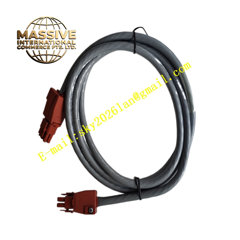
Description
Honeywell 51201397-002
Technical Specifications Multi-channel terminal block layout; built-in surge suppression and low-pass filtering; matched to Honeywell analog input I/O modules; screw-type field wiring terminals; metal mounting base for cabinet installation.
Functional Features Provides connection terminals for 4-20mA analog transmitters and voltage signal sensors. Integrates RC filter networks to suppress high-frequency electrical noise from field wiring. Contains transient protection components to clamp voltage spikes induced on instrument cables. Distributes field signals to the paired analog input module through internal ribbon or bus connections. Supports individual channel isolation and disconnection for calibration and maintenance.
Application Scenarios Chemical process measurement loops, boiler and furnace instrument cabinets, oil and gas process monitoring, water treatment analog instrument wiring and all Honeywell Experion DCS I/O cabinets.
Performance Parameters Low signal insertion loss; consistent filtering characteristics across all channels; fast transient response for surge protection; stable contact resistance for field wiring terminals.
Material Composition Mounting base is coated cold-rolled steel; terminal body is flame-retardant thermoplastic; terminal screws and conductors are nickel-plated copper; filter capacitors and suppression diodes are industrial grade through-hole components.
Structural Characteristics Flat assembly with grouped terminal channels; labeled terminal points for field positive, negative and shield connections; internal wiring jumpers for pairing with the I/O module; mounting holes for fixed installation inside control cabinets.
Working Principle Analog signals from field transmitters terminate at the screw terminals of this assembly. Signals pass through filter and surge protection circuits before being routed to the matched analog input module. The filtering network removes high-frequency interference while preserving the low-frequency process measurement signal. Protection components absorb voltage transients before they reach the sensitive I/O card electronics.
Installation Requirements Mount the assembly securely to the cabinet backplate or DIN rail. Route shielded instrument cables to the terminal points and apply single-point shield grounding. Follow Honeywell drawings to connect the ribbon cable between the terminal assembly and the analog input module. Label each channel according to the instrument loop tag number.
Precautions for Use Verify field transmitter power polarity before applying loop power. Do not use the assembly for high-voltage power wiring. Inspect terminal screw tightness periodically in vibration-prone cabinet environments.







