



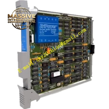
Description
Honeywell 51202329-201
Technical Specifications
- User control memory: 32 KB
- Connected I/O capacity: Up to 8 subracks, 512 I/O points
- Redundancy architecture: Dual-board hot standby synchronization
- Switchover time: ≤5 ms, bumpless output transfer
- Supply power: 5 V DC, ±15 V DC from backplane
- Operating temperature: 0 °C to +60 °C
- Sync link: Dedicated high-speed flat cable between paired boards
Functional Features Dual-card real-time state synchronization, primary and standby variables fully mirrored. Bumpless switchover, output value deviation ≤0.1% full scale during takeover. Independent hardware watchdog, automatic switchover on primary program runaway. On-board LEDs indicate primary mode, standby mode, sync link and fault status. Non-volatile program memory, no parameter re-download after power cycle. Diagnostic fault reporting to operator station.
Application Scenarios Critical process unit redundant control for TDC3000 systems High-availability boiler and reactor control loops Spare part replacement for failed redundant processors Redundancy upgrade for non-redundant TDC3000 process managers
Performance Parameters
- Sync data refresh rate: 0.5 ms
- Switchover output deviation: ≤0.1% full scale
- PID loop capacity: 64 loops per paired processor
- Mean time between failures: 800,000 hours
- Switchover test success rate: 100% for commissioned systems
Material Composition FR4 high-speed PCB substrate 32-bit industrial processor chip Synchronization logic FPGA Flash memory Optocoupler isolation devices Gold-plated backplane edge fingers
Structural Features Standard Eurocard dimensions. Front panel LEDs separately indicate primary mode, standby mode and sync fault. Dedicated sync flat cable connector on the board edge. Equal-length differential sync traces ensure consistent signal delay. Metal shielded front panel.
Working Principle After power-up, the two paired processors complete primary/standby role election. The primary board runs active control logic, collecting I/O data and executing PID calculations. The standby board receives all variables, parameters and intermediate state data in real time via the high-speed sync link, running identical logic without driving field outputs. The fault monitor circuit continuously checks primary processor heartbeat; when primary failure is confirmed, the standby board immediately takes over control output, with no process fluctuation. Sync link disconnection triggers unplanned switchover alarm.
Installation Requirements Install both paired boards in corresponding primary and standby slots. Connect sync flat cable between the two boards, lock connector clips. Download identical firmware and user program to both boards. Confirm sync status LED shows normal lock after power-up. Perform a forced primary fault test during commissioning, verify bumpless switchover.
Usage Notes Paired boards must run identical firmware revision; mismatched versions prevent sync handshake. Loose sync cable triggers unplanned switchover and process fluctuation; inspect connectors during maintenance. Never disconnect sync cables during operation, this disables redundancy function. Perform quarterly forced switchover tests to confirm standby processor readiness.







