



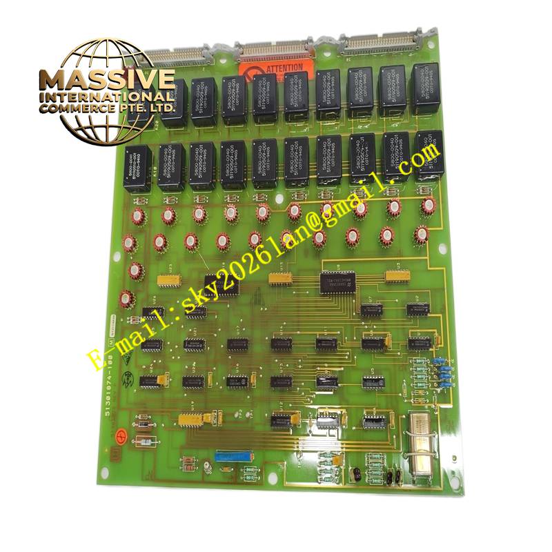
Description
Honeywell 51301874-100
Technical Specifications Multi-channel discrete digital input; dry contact or wet sensing capability; channel-level open circuit detection; backplane bus communication; 24V DC field sensing power option; front panel channel status LEDs.
Functional Features Detects the open and closed state of field discrete contact devices. Supplies or senses 24V DC field power for compatible two-wire proximity sensors. Diagnoses wire break faults on each input channel and sends fault alerts to the DCS alarm system. Transmits all channel status data to the controller through the rack backplane. Supports individual channel disabling during maintenance operations.
Application Scenarios Process valve position feedback, pump and motor auxiliary contact status, safety interlock switches, filter differential pressure switches and discrete alarm inputs in refinery and chemical DCS systems.
Performance Parameters Fast contact state sampling rate; reliable open-wire fault detection; high noise immunity for contact inputs; stable backplane data communication.
Material Composition PCB substrate is FR-4 flame-retardant multilayer board; input sensing circuits use industrial optocoupler isolation chips; backplane connector contacts are gold-plated; front panel is printed coated plastic with status LED cutouts.
Structural Characteristics Plug-in rectangular card for Honeywell DCS racks; front panel with individual LED indicators for each input channel; rear gold finger connector interfacing with the rack backplane; locking latches to secure the card in the slot.
Working Principle Field contact signals connect to the associated terminal assembly. Each input channel uses optocoupler isolation to separate field circuit potential from the control system internal logic. The module periodically samples each channel and converts contact states into digital values. Channel data is packaged and sent to the DCS controller over the backplane bus. Diagnostic logic compares measured values against expected circuit conditions to identify broken wires.
Installation Requirements Power off the rack before card insertion unless hot-swap is approved by system specifications. Insert the module into the correct I/O slot and lock the latches. Complete field discrete wiring to the paired terminal block. Test each channel by actuating field contact devices and verifying status changes in the DCS operator display.
Precautions for Use Do not route discrete input cables alongside high-power variable frequency drive cables. Confirm contact voltage ratings match the module sensing circuit. Use the module diagnostic functions to locate field wiring faults during commissioning.







