



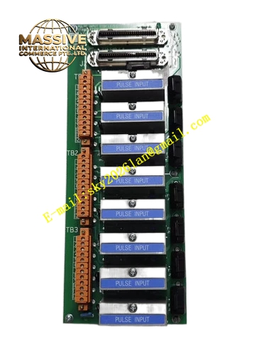
Description
Honeywell 51304084-125
Technical Specifications
- Channel Quantity: 12 pulse input channels
- Input Signal Type: Square wave pulse, contact closure pulse
- Input Frequency Range: 0.1 Hz to 100 Hz
- Input Voltage Range: 0 VDC to 30 VDC
- Isolation Rating: 250 VDC channel to backplane isolation
- Power Supply: 24 VDC from DCS rack backplane
- Operating Temperature: 0 °C to +60 °C
- Storage Temperature: -40 °C to +85 °C
- Relative Humidity: 5 % to 95 % non-condensing
- Mounting Form: Rack mounted termination assembly
- Signal Interface: Screw terminal field side, gold edge connector IOP side
Functional Features Independent RC filter network on each channel suppresses high frequency noise and contact bounce. Transient surge protection components absorb ESD and inductive spike from field pulse instruments. Channel isolation barrier prevents ground loop current from damaging the IOP processor card. Terminal marking silk screen clearly indicates positive, negative and shield pin assignment. Shield drain terminal provides single point shield grounding for field instrument cable. Open wiring loop can be detected by paired pulse IOP module through impedance measurement.
Application Scenarios Volumetric flow meter pulse signal wiring termination Turbine flowmeter and positive displacement meter pulse acquisition Tachometer speed pulse signal interface for rotating equipment Legacy TDC3000 DCS cabinet marshalling panel spare replacement Oil refinery and chemical batch metering control cabinet
Performance Parameters
- Input filter delay: Configurable from 2 ms to 50 ms
- Isolation withstand voltage: 250 VDC for 60 seconds
- Maximum pulse counting resolution: 1 pulse per cycle
- Surge withstand: 2 kV contact ESD per channel
- Terminal screw torque specification: 0.5 N·m to 0.7 N·m
Material Composition Base substrate: High TG FR4 multilayer PCB with UL94 V0 flame retardant grade Terminal block: Tin plated copper alloy screw terminal assembly Filter components: Metal film resistors, X7R ceramic capacitors Surge protection: TVS diodes and ferrite noise beads Connector: Gold plated phosphor bronze edge connector Housing support: Black glass filled nylon plastic support bracket
Structural Features Flat rectangular PCB assembly designed for installation inside DCS marshalling cabinet. Field wiring terminals locate on front side for convenient wiring and inspection. Rear edge connector directly mates with pulse input IOP ribbon cable or backplane adapter. Internal copper ground plane separates signal trace area and shield return path. Keying notch prevents mismatching with other FTA board slots. Mounting holes align with standard DCS cabinet rail spacing.
Working Principle Field pulse signal enters through screw terminal, passes through RC low pass filter and surge suppression circuit. Isolation component transfers pulse state across isolation boundary to output trace. Process pulse waveform maintains amplitude and edge integrity before transmitting to pulse IOP card. Shield wire connects to dedicated drain pin to divert common mode noise to cabinet protective earth.
Installation Requirements All connected DCS rack power must be de-energized before wiring or board replacement. Field pulse cable adopts twisted pair construction, shield connects only at this termination board. Separate pulse signal cable from high voltage AC power cable in cable tray. Tighten all terminal screws to specified torque value to avoid high resistance connection. Verify channel pulse count reading in DCS operator station after power restoration.
Usage Notes Do not inject AC voltage signal into pulse input terminals. Do not connect two grounding points on the same instrument cable shield. Do not remove or short the onboard surge suppression components. Wear anti-static wristband when handling this board. Clean terminal block periodically to remove conductive dust accumulation.







