



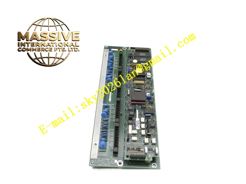
Description
Honeywell 51304156-100
Technical Specifications
- Monitored Power Rails: 5VDC, +12VDC, -12VDC, 24VDC
- Backplane Interface: TDC3000 proprietary backplane bus and direct power sampling taps
- Power Supply: Powered from rack backplane 5VDC rail
- Operating Ambient Temperature: 0°C to +60°C
- Storage Temperature: -40°C to +85°C
- Relative Humidity: 5% to 90% RH non-condensing
- Mounting Type: Plug-in slot installation on TDC3000 main rack
- Certification: UL, CE, RoHS
- Sampling Interval: 10ms
Functional Features It cyclically samples voltage value of every backplane power rail. It compares sampled voltage with configurable high and low alarm thresholds. It generates pre-warning alarm when voltage enters pre-fault range. It triggers power fail interrupt signal to main processor when voltage falls below critical threshold. It records voltage deviation value and fault timestamp into non-volatile memory. It carries front panel LED indicators for power normal, pre-fault and critical power fail. It supports hot swap replacement in redundant rack configuration. It uploads real-time voltage value and power fault log to TDC3000 operator station. It provides power quality trend data for cabinet maintenance analysis.
Application Scenarios TDC3000 main control rack backplane power supervision Petrochemical plant critical control node power health monitoring Refinery furnace control cabinet power fault early warning Power plant boiler interlock control rack power monitoring Chemical plant continuous process high-availability control node power supervision
Performance Parameters
- Voltage Sampling Accuracy: ±0.5% full scale
- Mean Time Between Failures: 880000 hours
- Insulation Resistance: Greater than 1000 MΩ
- ESD Immunity: 8kV contact discharge
- Power Fail Response Time: Less than 5ms after threshold crossing
Material Composition FR4 flame retardant conformal coated multilayer PCB Precision voltage sampling resistor divider network High-speed ADC sampling chip Threshold comparison logic chip Non-volatile memory chip for fault log storage Isolation components and surge protection circuit Gold plated edge connector for TDC3000 backplane Metal front panel with extraction handle and LED indicators
Structural Features Standard TDC3000 paddle card form factor. Front panel integrates grouped LED status indicators and extraction handle. Rear gold plated edge connector mates with rack backplane power taps and control bus. Internal PCB layout separates high-current power sampling trace and low-voltage logic circuit to reduce noise interference. Anti-key notch prevents reverse insertion into rack slot. Locking clip secures module firmly after installation. Conformal coating covers PCB surface to resist industrial cabinet moisture and dust.
Working Principle After receiving 5VDC supply from rack backplane, the module completes self-test and initializes threshold parameters. Sampling divider network converts each backplane rail voltage into measurable range for ADC chip. ADC converts analog voltage value into digital data. Logic chip compares measured value with preset alarm and critical thresholds. If voltage enters pre-fault zone, pre-warning flag generates and uploads to operator station. If voltage drops below critical threshold, power fail interrupt signal sends to main processor to trigger orderly saving of control logic and graceful shutdown. Fault event and voltage snapshot are stored in non-volatile memory.
Installation Requirements Wear anti-static wrist strap before inserting module into dedicated power monitoring slot of rack. Lock extraction handle after alignment. Confirm sampling taps connect to all target power rails on backplane. Configure voltage alarm and critical threshold parameters in engineering workstation. Power on rack and verify power normal LED steady on. Test pre-fault and power fail alarm function by adjusting rack power supply voltage. Confirm processor executes graceful shutdown when critical threshold is reached.
Usage Notes This module must connect to all required power sampling taps on backplane. Do not modify internal sampling resistor network. Do not remove module while control node is running critical process loops. Replace module when voltage reading deviation exceeds specification. Keep cabinet ventilation stable to avoid power supply thermal drift.







