



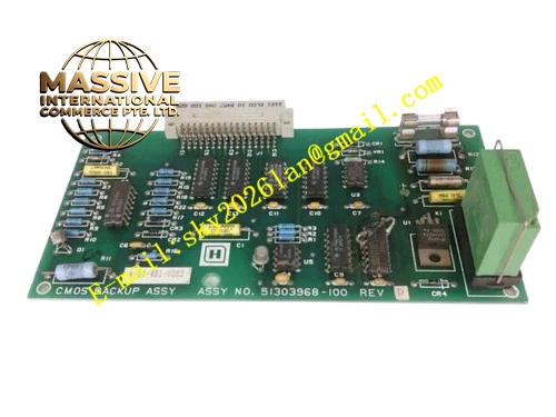
Description
Honeywell 51304481-100
Technical Specifications
- Channel count: 16 analog input channels
- Signal types: 4–20 mA, 1–5 V DC
- Resolution: 16-bit ADC
- Channel isolation: 500 VAC between field side and backplane
- Loop power: 24 V DC, 20 mA per channel
- Backplane interface: TDC3000 I/O subrack bus
- Operating temperature: 0 °C to +60 °C
Functional Features Per-channel on-board loop power supply, eliminates external transmitter power. 16-bit high-resolution ADC, measurement accuracy ±0.1% full scale. Wire break detection per channel, triggers channel fault on open circuit. Digital filter smooths sampled values, suppresses field signal noise. On-board LEDs indicate card power, communication and fault status. Hot swap support, card replacement without subrack shutdown.
Application Scenarios Temperature, pressure and flow transmitter signal acquisition for TDC3000 loops Spare part replacement for failed analog input cards Analog I/O expansion for existing TDC3000 subracks High-precision process measurement loops
Performance Parameters
- Conversion accuracy: ±0.1% full scale
- Update rate: 20 ms full channel scan
- Common mode rejection ratio: ≥90 dB
- Wire break detection response: ≤200 ms
- Mean time between failures: 500,000 hours
Material Composition FR4 low-noise PCB substrate 16-bit ADC chip Instrumentation amplifier array Optocoupler isolation devices TVS surge protection diodes Gold-plated backplane edge fingers
Structural Features Standard Eurocard dimensions, inserts into TDC3000 I/O subrack slots. Front screw terminals arranged for 16 channel wiring. Isolation barrier separates field side and backplane logic side. Front panel LEDs show card run and fault status. Anti-keying notch prevents insertion into non-analog slots.
Working Principle Field transmitter signals connect to input terminals. On-board 24 V DC loop supply powers the field transmitter. 4–20 mA signals pass through the instrumentation amplifier, routed to the 16-bit ADC for conversion. Digital filter averages consecutive samples to reduce noise. Wire break detection monitors loop current; open circuit triggers channel fault flag. Converted engineering values are packaged into bus frames, transmitted to the process manager over the subrack backplane.
Installation Requirements Insert the card into a dedicated analog input slot in the I/O subrack. Wire field transmitters to labeled channel terminals, observe signal polarity. Configure input range per channel in TDC3000 system software. Verify channel values read correctly after power-up.
Usage Notes Never apply AC high voltage to input terminals, this destroys the ADC input circuit. Shielded cable for transmitter wiring reduces EMI noise. Channel wire break faults require field wiring inspection; resolve open circuits before resetting alarms. Total loop supply current must not exceed 320 mA across 16 channels.







