



Description
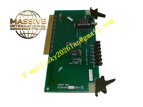
HONEYWELL 51304650-100
Technical Specifications Multi-conductor flat ribbon cable construction Integrated foil shielding layer Custom fixed length for rack internal wiring Molded male and female connectors at two ends Industrial flame retardant insulation material Exclusive pin definition matching Series A I/O modules and FTA terminal bases
Functional Features Transmit multi-channel parallel signals between I/O module and FTA terminal base Shielding layer suppresses cabinet electromagnetic interference and noise Reduce signal crosstalk between adjacent signal channels Maintain stable transmission quality for analog and digital signals Pre-assembled connectors enable fast installation and replacement Isolate signal path from power circuit interference
Application Scenarios Experion PKS DCS I/O cabinets in chemical, refinery and power generation plants Internal interconnection between Series A I/O cards and FTA terminal assemblies Signal distribution inside control marshalling cabinets
Performance Parameters Operating temperature range 0℃ to 60℃ Relative humidity 5% to 95%, non-condensing Low signal attenuation during signal transmission Resist mechanical vibration inside control cabinet Maintain stable connector contact performance under long time continuous operation
Material Composition Solid copper inner conductors PVC flame retardant insulation material Aluminum foil shielding layer Plastic molded connector housing Gold plated contact pins inside connectors
Structural Features Flat multi-conductor ribbon cable structure Molded integrated connectors at both cable ends Strain relief structure at connector root to prevent cable fracture Part number and specification printed on cable outer label Fixed pin assignment to match I/O and FTA pin definition
Working Principle Each independent conductor inside the ribbon cable carries separate channel signals between I/O module and FTA terminal base. The aluminum foil shielding layer connects to cabinet protective ground to block external electromagnetic noise. Multi-parallel wire structure transmits multiple channel signals simultaneously with controlled crosstalk. Molded connectors ensure precise pin alignment and reliable electrical contact between matched hardware.
Installation Requirements Arrange cable routing inside cabinet with specified minimum bending radius and avoid sharp bending Insert connectors fully and lock connector latches completely Fix cable using cable ties to prevent pulling force caused by cabinet vibration Separate ribbon cable routing away from high-current power cables Check pin definition consistency before powering up the cabinet
Precautions for Use Do not apply strong pulling force to cable during installation Prevent sharp metal objects scratching cable insulation surface Do not bend cable below minimum bending radius Inspect connector pins for bending, oxidation and corrosion during routine maintenance Replace whole cable assembly directly once insulation damage occurs







