



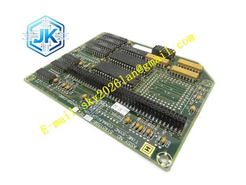
Description
Honeywell 51309208-150
Technical Specifications
- Brand: Honeywell
- Part Number: 51309208-150
- Product Type: DCS system hardware module
- Applicable Platform: Honeywell DCS/process control hardware platform
- Mounting Method: Standard rack plug-in installation
- Signal Type: Control, communication, I/O, or system management
- Channel Count: Subject to nameplate and official manual
- Power Supply: Powered by system cabinet or backplane
- Operating Environment: Industrial control room cabinet environment
- Certification: Subject to nameplate and official documentation
Functional Features
- Functions as part of a Honeywell process control hardware platform.
- Can support control, communication, I/O, power, or auxiliary system functions.
- Works with system racks, backplanes, power supplies, and communication networks.
- Supports process data acquisition, control output, or system communication.
- Provides status indication and fault monitoring depending on module type.
- Suitable for maintenance, replacement, and spare inventory management.
Application Scenarios
- Honeywell DCS daily maintenance
- Control station or I/O station hardware replacement
- Module replacement during planned shutdowns
- Chemical, power, metallurgical, pharmaceutical, and other process industry applications
- Control cabinet module expansion or upgrade
- Spare parts inventory and emergency replacement
Performance Parameters
- Operates within a Honeywell process control system platform.
- Processing capability, communication rate, isolation level, power consumption, and environmental ratings must be confirmed from official documentation.
- If used as a controller or communication module, performance depends on system version and network configuration.
- If used as an I/O module, performance depends on field signal type and wiring configuration.
Material Composition
- Industrial-grade printed circuit board
- Metal or engineering plastic housing
- Backplane connector
- Status indicator LEDs
- Fixing latches or rail mounting components
- Conformal-coated circuit assemblies
Structural Features
- Standard rack plug-in structure.
- Front panel includes status indicators, labels, and interface markings.
- Rear side connects through a backplane or dedicated connector.
- Compact design suitable for dense cabinet installation.
- Part number 51309208-150 is marked on the module label for identification.
- Maintains compatible mounting dimensions with the same hardware family.
Working Principle
The module performs a specific system function depending on its type. If it is a controller-related module, it participates in control execution and data exchange. If it is a communication module, it transfers data among controllers, operator stations, servers, or I/O networks. If it is an I/O-related module, it acquires field signals or generates control outputs. If it is a power or auxiliary module, it provides power distribution, monitoring, or protection. The module communicates with other hardware through the system backplane, communication network, or I/O link.
Installation Requirements
- Confirm the system is in a safe maintenance state before installation.
- Verify that 51309208-150 matches the system configuration and original module.
- Confirm the slot position, rack type, and backplane version are compatible.
- Align the module carefully with the connector to avoid pin damage.
- Ensure the module is firmly seated and indicator status is normal.
- Check cabinet power supply, grounding, and communication links.
- After replacement, verify system alarms, communication status, and control loop status.
- Perform online checks or offline verification when required.
Precautions for Use
- Do not insert or remove the module without confirming maintenance procedures.
- Do not replace it with a different part number without verification.
- Protect the module from electrostatic discharge, moisture, high temperature, and vibration.
- Record system status, alarms, and original module labels before replacement.
- Store spare modules in anti-static, dry, and non-corrosive environments.
- If the module shows physical damage, connector oxidation, or abnormal indicators, further inspection is required.
- Exact function, terminal definition, and parameters must be confirmed by Honeywell official documentation and the physical nameplate.







