



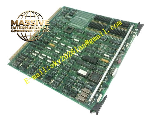
Description
Honeywell 51400901-100
Technical Specifications
- Backplane Interface: TDC3000 processor dedicated backplane bus
- Power Supply: 5VDC and 12VDC from rack backplane
- Operating Ambient Temperature: 0°C to +60°C
- Storage Temperature: -40°C to +85°C
- Relative Humidity: 5% to 90% RH non-condensing
- Mounting Type: Plug-in slot installation on TDC3000 processor rack
- Certification: UL, CE, RoHS
- Watchdog Timeout Period: 100ms
Functional Features It sends continuous watchdog heartbeat signal to main control processor. It monitors heartbeat response from main processor continuously. It triggers automatic processor failover when heartbeat timeout is detected. It synchronizes real-time clock between primary and standby processor. It monitors backplane power supply voltage and detects power loss warning. It stores processor fault log and failover record in non-volatile memory. It carries front panel LED indicators for power, primary processor active, standby processor active and fault. It uploads processor failover event and fault log to TDC3000 operator station. It supports hot swap replacement in redundant processor rack.
Application Scenarios TDC3000 redundant processor rack auxiliary monitoring board Petrochemical plant critical control node processor failover management Refinery furnace safety control processor rack Power plant boiler interlock control redundant processor cabinet Chemical plant continuous process high-availability control node
Performance Parameters
- Failover Trigger Time: Less than 150ms after watchdog timeout
- Mean Time Between Failures: 870000 hours
- Insulation Resistance: Greater than 1000 MΩ
- ESD Immunity: 8kV contact discharge
- Clock Synchronization Error: Less than 1ms
Material Composition FR4 flame retardant conformal coated multilayer PCB Watchdog logic chip and real-time clock chip Fault log non-volatile memory chip Power voltage sampling circuit Backplane bus transceiver chip Isolation components and surge protection circuit Gold plated edge connector for TDC3000 processor backplane Metal front panel with extraction handle and LED indicators
Structural Features Standard TDC3000 paddle card form factor. Front panel integrates grouped LED status indicators and extraction handle. Rear gold plated edge connector mates with processor dedicated backplane bus. Internal PCB layout separates watchdog logic circuit and clock circuit to avoid timing interference. Anti-key notch prevents reverse insertion into rack slot. Locking clip secures module firmly after installation. Conformal coating covers PCB surface to resist industrial cabinet moisture and dust.
Working Principle After power supply from rack backplane, the module starts watchdog timer and sends heartbeat signal to main processor. Main processor returns response signal after receiving heartbeat. If response signal is not received within timeout period, auxiliary board triggers failover signal and switches control authority to standby processor. It samples backplane voltage continuously and generates power pre-fault alarm when voltage drops below threshold. It records fault event and timestamp into non-volatile memory. Clock synchronization circuit aligns time of primary and standby processor.
Installation Requirements Wear anti-static wrist strap before inserting module into dedicated auxiliary slot of processor rack. Lock extraction handle after alignment. Complete backplane bus connection with primary and standby processor boards. Configure redundant failover parameter in engineering workstation. Power on rack and verify primary processor active LED steady on. Test failover function by forcing main processor fault. Confirm control logic runs continuously without interruption.
Usage Notes This module must be matched with corresponding main processor hardware version. Do not remove module while redundant control node is running. Do not modify internal watchdog timeout parameter. Replace module when processor failover function cannot be triggered normally. Keep cabinet temperature stable to guarantee clock accuracy.







