



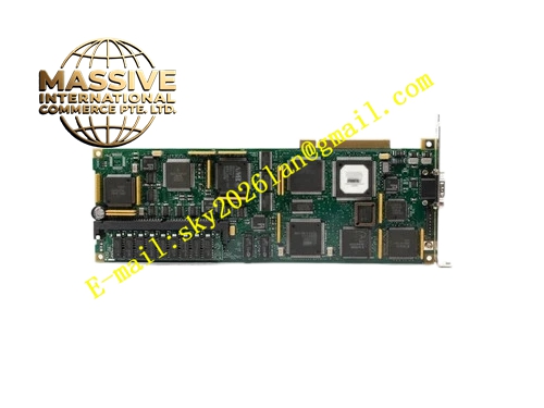
Description
Honeywell 51400993-100
Technical Specifications
- Video output: Analog RGB 1280 x 1024 resolution at 60 Hz refresh rate
- Memory: 4 MB graphics frame buffer
- Interface: TPS operator station VME bus
- Supply power: 5 V DC from station backplane
- Operating temperature: 0 °C to +60 °C
- Supported monitors: Industry-standard VGA RGB monitors
- Color depth: 24-bit true color output
Functional Features Renders static process mimic diagrams and dynamic process value updates at 30 frames per second. On-board graphics accelerator offloads rendering work from the station main processor. Supports alarm color flashing, status color change for field device state. On-board LEDs indicate graphics board power, video output active and fault status. Hot swap support, faulty board replacement without full station reboot. Compatible with all TPS series operator station monitor models.
Application Scenarios Process display rendering for TPS control room operator stations Spare part replacement for no-video output and color distortion faults in legacy stations Monitor upgrade retrofits for aging CRT-based operator stations Graphics board replacement during operator station hardware refresh
Performance Parameters
- Frame buffer refresh latency: ≤33 ms
- Video signal output level: 0.7 V peak to peak RGB
- Resolution accuracy: 1 pixel precision
- Mean time between failures: 350,000 hours
- Operating humidity: 10% to 90% non-condensing
Material Composition FR4 high-speed PCB substrate Graphics processing ASIC chip Frame buffer DRAM chips RGB video DAC chips VGA output connector Gold-plated VME edge fingers
Structural Features Standard VME form factor board. Front panel houses 15-pin D-sub RGB video connector. LED array shows board power, video sync and fault status. Metal shielded front panel contains high-speed graphics circuit radiation. Mounting bracket locks to the operator station chassis.
Working Principle After power-up, the board receives graphics command data from the station main processor over the VME bus. The on-board graphics accelerator renders process mimic geometry and dynamic text into the frame buffer DRAM. The video DAC converts digital frame buffer data to analog RGB signals, output to the connected monitor. The board continuously refreshes the frame buffer as process values update, rendering live process changes on the monitor display. Fault monitor circuit checks board memory and video signal lock; abnormal state triggers a board fault flag.
Installation Requirements Power off the operator station before board replacement. Insert the graphics board into the dedicated VME slot, press evenly until gold fingers are fully seated. Connect monitor RGB cable to the D-sub connector, tighten the fixing screws. Power on the station, verify display output renders correctly with no color distortion.
Usage Notes Never plug or unplug the monitor cable while station power is on, this damages the video DAC output circuit. Monitor cable shield must be grounded at the monitor end to prevent screen noise. Graphics board memory failure causes screen artifacting; replace the board immediately on visual artifacts. High-voltage monitor cables routed near the operator station cause screen interference.







