



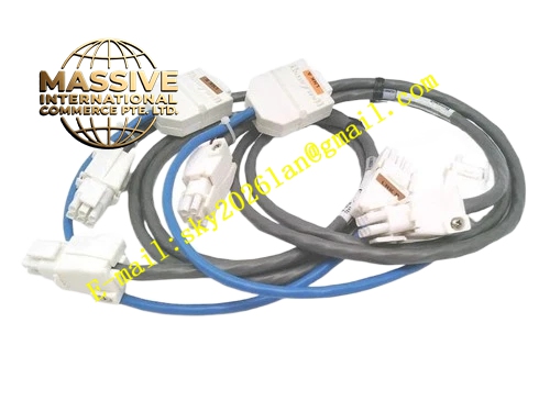
Description
Honeywell 51403776-100
Technical Specifications Rated operating voltage 24VDC; fixed speed axial fan structure; built-in hall-effect speed detection sensor; airflow matches heat dissipation requirement of DCS node rack; operating temperature 0℃ to 60℃; storage temperature -40℃ to 85℃; relative humidity 5% to 95% non-condensing; rack mounting bracket integrated; fan fault contact output; UL and CE certification.
Functional Features It generates forced airflow to take away heat dissipated by rack electronic modules. It continuously detects fan rotating speed through built-in speed sensor. It triggers fan fault alarm when rotating speed drops below threshold or fan stalls. It provides dry contact fault signal output to rack diagnostic circuit. It adopts modular integrated design for quick replacement during maintenance. It reduces internal rack hot spot to prevent over-temperature shutdown of processor cards.
Application Scenarios Cooling fan replacement for refinery TDC3000 node racks; heat dissipation fan assembly for chemical plant legacy DCS control cabinets; spare fan unit for Honeywell history module and universal station racks; forced cooling component for petrochemical plant old TPS system node cabinets.
Performance Parameters Fan service life meets industrial continuous operation requirement; speed sampling response time is less than 2 seconds; airflow attenuation is controlled within specification under long-term dust accumulation; fault contact insulation resistance meets rack diagnostic circuit requirement.
Material Composition Fan frame and blade adopt high-strength flame retardant plastic; motor bearing is long-life sintered metal bearing; mounting bracket is cold rolled steel with powder anti-rust coating; speed sensing circuit board is FR4 PCB; terminal conductive parts are tin-plated copper alloy.
Structural Characteristics Integrated fan and bracket assembly; pre-drilled mounting holes matching legacy DCS rack structure; fan air inlet and outlet with dust-proof mesh; wiring terminal block for 24VDC power and fault signal output; overall lightweight design convenient for rack installation and disassembly.
Working Principle After 24VDC power supply is connected, the fan motor drives the blade to rotate and form directional cooling airflow inside the rack. The hall sensor detects real-time rotating speed and transmits speed signal to the on-board diagnostic circuit. When fan stalls or speed drops below preset threshold, the circuit changes the state of fault dry contact, and the rack controller captures this signal and generates fan fault alarm in DCS operator station.
Installation Requirements Fix the fan assembly to the designated air duct position of DCS rack with mounting bolts. Confirm airflow direction matches rack cooling design before installation. Connect 24VDC power and fault signal wires to the terminal block. Keep the air inlet mesh unobstructed and away from large cable bundles. Ensure cabinet grounding is reliable.
Usage Notes Cut off 24VDC power supply before fan disassembly and replacement. Clean dust mesh regularly to prevent airflow blockage and over-temperature. Do not touch rotating fan blade after power-on. Test fan fault alarm function by blocking blade after installation. Replace the whole assembly when bearing noise increases obviously.







