



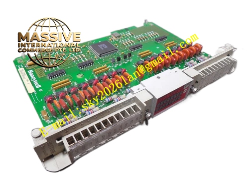
Description
Honeywell 620-0007R
Technical Specifications
- Communication Bus: Honeywell proprietary I/O Link bus
- Fiber Type: Single mode optical fiber
- Optical Wavelength: 1310 nm
- Maximum Transmission Distance: 20 km
- Supported Baud Rate: 375 kbps and 750 kbps configurable via DIP switch
- Optical Output Power: Less than 0.5 mW
- Receiver Sensitivity: -31 dBm
- Electrical Interface: Differential copper I/O Link terminal
- Isolation Rating: 1500 VAC galvanic isolation between copper side and fiber side
- Operating Temperature: 0 °C to +60 °C
- Power Supply: 5 VDC from IPC620 backplane
- Form Factor: Standard plug-in IPC620 rack card
Functional Features DIP switch bank selects communication baud rate and pull-up / pull-down resistor configuration. Optical signal loss detection circuit triggers fault flag when fiber cable breaks or attenuation exceeds limit. Built-in signal reshaping circuit recovers distorted differential signal received from copper bus. Front panel LED displays power supply status, optical transmit activity, optical receive activity and link fault. CRC check mechanism validates all communication frames transmitted across fiber channel. Point-to-point topology prevents bus conflict on I/O Link network. Surge suppression components protect copper differential terminals from ESD and lightning induced spike.
Application Scenarios Long distance remote I/O station connection for IPC620 PLC system Substation control room separated from field equipment by several kilometers Industrial sites with heavy electromagnetic interference such as power plant and steel mill Process Manager controller remote expansion fiber communication upgrade Legacy IPC620 copper I/O link intermittent communication fault spare replacement
Performance Parameters
- Link propagation delay: 3.2 µs maximum
- Optical budget: 18 dB
- Frame error rate: Less than 1 × 10⁻¹² under normal attenuation
- Fault reporting latency: Less than one I/O Link communication cycle
- Differential common mode noise rejection ratio: 70 dB minimum
Material Composition PCB substrate: FR4 multilayer UL94 V0 circuit board Optical devices: Single mode laser transmitter and PIN photodiode receiver Signal processing: High speed differential line receiver and driver IC Protection components: TVS diodes, ferrite beads, metal film resistors Connector: Gold plated backplane edge connector, LC fiber receptacle Front panel: Black flame retardant plastic with LED array and DIP switch access cover
Structural Features Standard eurocard plug-in dimension compatible with IPC620 rack slot. LC fiber port arranged on front panel for convenient fiber patch cord connection. DIP switches locate behind small removable plastic cover to avoid accidental parameter change. Internal isolation barrier separates electrical circuit zone and optical transceiver zone. Anti-keying notch prevents wrong insertion into other IPC620 module slots. Trace layout isolates high speed differential copper traces from low speed logic traces.
Working Principle Differential electrical I/O Link signal from backplane enters driver circuit and converts into modulated laser optical signal. Laser signal transmits along single mode fiber to remote matching fiber converter module. Remote module converts optical signal back into restored differential electrical signal for remote I/O station. Inbound optical signal from remote end converts back to electrical signal and sends to controller backplane. Optical power monitoring circuit detects insufficient received light level and raises link fault alarm.
Installation Requirements Power down rack before module installation or DIP switch configuration. Use single mode LC-LC patch cord matching this module specification. Set identical baud rate value on paired local and remote converter modules. Fiber cable routing must avoid sharp bending with bending radius larger than 30 mm. Verify I/O Link communication status in controller diagnostic menu after power restoration. Clean LC fiber connector end face before plugging into module port.
Usage Notes Do not look directly into active optical transmitter port. Do not use multi-mode fiber cable with this single mode variant. Mismatched baud rate setting causes permanent I/O link communication failure. Dust contamination on fiber end face increases attenuation and triggers intermittent link fault. Do not modify onboard pull resistor network.







