



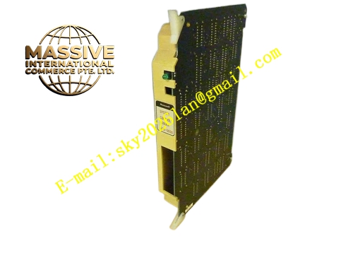
Description
Honeywell 620-0030
Technical Specifications
- Processor Core: 32-bit industrial RISC processor
- Program Memory: Flash memory, 2 MB capacity
- Data Memory: Battery backed SRAM, 512 KB
- Logic Scan Cycle: Configurable from 1 ms to 100 ms
- I/O Bus Interface: IPC620 proprietary I/O Link backplane bus
- Network Communication: EIA-485 serial port for Modbus RTU host communication
- Operating Temperature: 0 °C to +60 °C
- Power Supply: 5 VDC and 24 VDC from rack backplane
- Redundancy Support: Hot redundant CPU pairing
- Hot Swap Support: Not supported
Functional Features Execute ladder logic, function block and structured text control program cyclically. Built-in PID function block for continuous process closed loop regulation. Battery backed SRAM retains setpoint, alarm and runtime data during power outage. Hardware watchdog timer resets CPU automatically if program execution stalls. Self-diagnostic continuously monitors memory, bus, power and internal circuit. Front panel multi-color LED indicates run state, fault state, communication activity and redundancy status. Event sequence capture records discrete input change with millisecond timestamp for SOE function. Modbus RTU port exchanges process data with HMI and upper level SCADA system.
Application Scenarios Continuous chemical process sequence and regulatory control Water treatment plant integrated PLC control system Packaging machine and material handling automation control Power auxiliary equipment interlock and monitoring system Redundant IPC620 control system CPU spare replacement
Performance Parameters
- Boolean logic execution speed: 0.1 µs per boolean instruction
- PID calculation execution time: Less than 120 µs per loop
- Battery data retention time: Minimum 72 hours at 25 °C ambient
- Watchdog timeout: 500 ms fixed
- Modbus RTU communication update rate: Configurable
Material Composition Multilayer high TG FR4 PCB, 32-bit RISC processor IC, flash memory chips, static RAM chips, lithium backup battery assembly, bus buffer logic IC, decoupling tantalum and ceramic capacitors, gold plated backplane edge connector, black flame retardant plastic front panel with extraction handle and status LED window.
Structural Features Standard eurocard plug-in form factor for IPC620 CPU rack slot. Front panel LED indicators separate run, fault, network and redundant status. Rear gold edge connector mates with rack backplane I/O Link bus and power rail. Internal metal shielding cover reduces EMI interference to processor and memory circuit. Anti-keying notch prevents reversed insertion into I/O module slot. Sealed battery compartment prevents electrolyte leakage contamination of PCB traces.
Working Principle CPU loads user control program from flash memory after power up and starts cyclic scan. In each scan cycle, CPU reads all remote I/O status over I/O Link bus, executes logic and PID calculation, generates output command and sends command back to I/O modules. Redundant CPU synchronizes program state and process data continuously with primary CPU. If primary CPU fails, secondary CPU takes over control without process interruption. Watchdog circuit monitors program execution flow and triggers reset when scan cycle overflows. Backup battery supplies SRAM power during rack power loss.
Installation Requirements Fully power down IPC620 rack before CPU module installation or replacement. Align orientation mark and insert card fully into CPU dedicated slot. Download compiled control program to CPU after power restoration. Set scan cycle time, redundancy mode and Modbus communication parameters. Check backup battery voltage in CPU diagnostic menu periodically.
Usage Notes This module does not support hot swap operation. Do not remove backup battery while module remains powered. Battery has fixed service life and requires scheduled replacement. Program download operation can override existing running control logic. Static protection wristband must be worn when handling CPU module.







